New Tools!!!

Tuesday 29th July 2008 1hr 30min
Cut tie-down brackets and tapped for rings. Began edge-prep of main and leading edge nose ribs.

I went out yesterday evening to buy the lumber I need for the wing stand and the flat table for the flaps and ailerons. I was very happy with the 4X2 lengths I got. They are 8ft so there will be no wastage. More importantly they are dead straight and heavily grained so they should resist warping. I will glue and screw two lenghts back-to-back to make the posts for the wing stand. I could only get half-inch MDF so I got two sheets and had them ripped in the store. I will glue two layers together on each side of the frame.

Always nice when you get a box of new tools in the post. Included was a low-value torque wrench, a heavier mushroom-head bucking bar that lots of people find very good on the wing skins and a tap for the tie-down brackets, as well as the rings themselves. I had decided to stick with the drop-forged items with their American thread patterns because using localy sourced eye-bolts would have meant drilling out the holes to a metric size and tapping accordingly. This would have been the only metric fitting on the plane and might be confusing to anybody other than myself. Some Torque Seal to identify torqued-up bolts, Permagrit countersinks in #30 and #40 for fibreglass work and a 21/64 drill bit as recommended by Smitty for the Delrin aileron stops made up the rest of the consignment. I am going to need a quarter-inch to three-eights drive adapter and a set of 'crows feet' for the torque wrench - I don't know what possessed me to order the quarter inch drive because my socket set is virtually all three-eight.


Boy, my band saw made a fuss about cutting these tie-down sections. I use a 16tpi blade and it seemed to be melting its way through the metal rather than cutting. Luckily, I had left plenty of margin and I got things nicely cleaned up with the sanding belt and the polishing wheel. Actually tapping the holes was a non-event. I used Beo-Lube (another item in today's goody-bag) and repeatedly went two turns forward and half a turn back, ocassionally coming all the way out to blow off the shavings and re-lubricate. the tap is only just long enough though I went as far as it would let me. I may have to shorten the threaded portion of the rings so that the flange of the rings seat up against the wing skins, although having a slight gap under the flanges might be a blessing for the paintwork. I will decide when the plane is finished and painted.
I made a start on the edge - preparation of the main ribs. This is going to take forever!

Picking up the pieces


Sunday 27th July (8hr 10min)

Match-drilled reinforcing plates W-907B, C, D and E to the W-907A left and right aft spars. Deburred and edge-prepped all parts. Cut aileron push rod openings in W907D left and right. Countersunk W907C per plans. Dimpled W-907A top flange in way of W907D doubler fork.

I spent Friday in bed with a very heavy cold - no temperature, just feeling sick and very drowsy. By Saturday afternoon, I was definitely on the mend and I felt pretty good this morning with only a little congestion to suggest that I was ever sick. I think I got off lightly. I made the Michael Bublé gig by the way - really enjoyable.

Despite the good news from Vans regarding replacements, it was a sad business to put away the underbent spars. It would have been an interesting challenge to make the repair that Vans suggested but very hard to go right through the process of building the main wing structure with the fear that the stresses of re-bending would emerge as a result of riveting on the top skins and leave me with 'wrinkly wings' through no fault of my own.

I quickly got back into the swing of things by working on the aft spars. I am continuing my plan of carrying out each process on the parts for both wings at the same time. There were no particular problems here but there are a few things to watch out for. All the builders' sites refer to the need for care in deciding which holes on the W-907C doubler plate to countersink and which holes on all the doubler plates to leave open until later. With the help of the plans and these sites, I did not find those issues difficult.

However, what did make me scratch my head was that I seemed to be missing several pre-punched holes on the spar. These holes are for rivets to attach the lower edge of the flap and aileron gap fairings, where they join the W907-D (mid-span) and E (outboard) doubler plates (not the W-907C - its holes are all present and correct). The plans show all six of these holes but they do not exist on the spars and therefore can't be match-drilled through the doubler plates along with the rest. The holes are all pre-punched on the gap fairings themselves so the only option appears to be to match-drill them in assembly with the doubler plates and aft spar using the fairing holes as a guide. I could have done this on the spot but I thought it might be better if the fairings could be clecoed to the skins at their top edge as well as to the spars at their lower edge. In this way, I can be certain that these tabs are hitting the doubler plates at precisely the right point. I better put it on a 'to-do' list so that I don't forget it while the top skins are on for match-drilling.

The other point that wasn't easy to spot, was the fact that the last three outboard rivets through the aft spar and outboard doubler plate (W-907E) need to be flush on the aft side. they will later be covered by an angle associated with the aileron hinge, which is riveted through the neighbouring row of holes. The plans make clear reference to this (if you are careful about reading ALL the notes) but they do not specify whether dimpling or countersinking is appropriate. Some builders have countersunk the doubler plate (leaving the spar untouched) but I think this material is too thin. I need to research this. Somewhere there must be a table giving minimum plate thicknesses for various sizes of countersink. The top flange of the spar was dimpled for the skins so dimpling should not be a problem as the W-907E is made of the same .040 material UPDATE! Section 5 of the manual specifies .050 as the minimum thickness for #30 countersinks, unless the plate to be countersunk is sandwiched between two others, so I have decided to dimple the doubler and countersink the spar, which will be sandwiched between the doubler and the rib on the opposite side


Vans comes through

Friday 25th July

Vans agree to ship new spars

It turned out that Terry Elgood changed his mind and regrets not getting new spars. Waves and mismatches between skin edges appeared on his wings only after riveting on the skins - even though the spars had appeared perfectly straight after the re-bending operation. Also, my Inspector Mick Bevan was not very happy about trying to fix such a major part 'in the field'. I pointed this out to Ken Scott and also said that it was important to me that any flaws in my plane should be my own fault and not anybody else's.

Having made my case, and after a short period of reflection, Ken came back and said they would replace the spars. Maybe it was no more than my rights but I still felt great that Vans had stood by me and honoured their side of the bargain. The mark of a truly great company is not that things never go wrong but how well they respond when problems do arise. Clearly Vans are a great company.

Only trouble is that I am going down with a stinking cold; two days before the annual SAAC fly-in and a Michael Bublé concert (separate event - our fly-ins are rather more low-key) next Saturday.

Wing spar bender

Monday 21st July 2008. 1 hr

Riveted platenuts to bottom flange of left wing spar. Found major manufacturing fault. Contacted Vans.

I went back to work on the wing spar this evening and completed riveting all the platenuts on the bottom flange of the left spar, including the #6 platenuts for the three inspection plates.

When you have got a lot of anything to do, I find it better to break it down into its parts and approach it production-line style. For example on this job, rather than making a separate job of each platenut, I did all of them together following these steps:

  1. Cleco one 'lug' of every platenut in place.
  2. Put rivets in the other lug of every platenut.
  3. Squeeze all of these rivets.
  4. Replace the clecos with rivets in the 2nd lug of each platenut and
  5. Squeeze these rivets.
It means, for instance, that you don't pick up and put down the cleco pliers twice for each platenut; you pick it up and put it down twice for all 31 or 43 on the same flange. The job goes faster because you build up skills more quickly and you allow the learning curve to operate. For this reason, I intend to build both wings together to the greatest extent possible.


When I turned the spar around to begin the platenuts on the top flange, I happened to sight down along the flange and noticed immediately that it was not square to the web. The picture shows my set-square held with its blade along the outside of the web and you can clearly see the gap under the corner of the 'stock'. My protractor showed that it was, in fact, 6 degrees underbent (96 degrees between web and flange). I checked the other spar, which was still in its polythene and it is precisely the same. I offered up a rib to the spar in case it was meant to be like this and found that the flange should, in fact, be about the same amount off vertical in the other direction if it is to match the slope of the rib top flange at this point. There is a gap of about 10 to 12 degrees between the two parts. Clearly, a wing can't be built on the basis of these spars in this condition.

I remembered an article on page 10 of the latest RVator, telling the story of Terry Elgood, a Canadian builder who had the same problem. Terry fixed his spars by cutting a notch in the end of a length of oak and bending the flange back to its proper position by using putting the notch over the flange and levering it, little by little, working up and down along the length of the spar moving only an inch or less at a time.

I am deeply suspicious of this. I can't see how you can get a straight flange out of this procedure as the lever is exerting a point load on a very short section of flange at a time. In fact I think I see some waves in the lip of Terry's flange in the photos but the resolution is not high enough to be sure. I remembered thinking how convenient for Vans if builders, especially those at a great distance from Aurora, would be so good as to fix Vans quality problems and save them from shipping expensive replacement parts to the four corners of the globe.

Before hysteria took over, I rang Vans support and Ken answered. He was sympathetic of course and embarrased that it had happened but basically he is happy that Terry Elgood's method makes the issue go away and its up to me to implement it. To be fair, he said they would "make it right" whatever that means. However, I couldn't make him say that he would replace the spars if the repair went wrong. I have to think about this some more.

NOT a good day!

The shock of the Big!

Sunday 20th July 2008. 5 hrs 30 min

Completed inventory and storage of wing kit. Countersunk left wing for tank attach and inspection plates

Just before putting the emp away, I wanted to check that the rudder hinges were set up okay. Unlike the elevator hinges, access to insert bolts is very restricted, particularly for the top two rod-end bearings. Not having any suitable nails, I used some allen keys, one of which had to be cut to fit - no biggie as it was a cheap freebie that had come with some self-assembly furniture. The hinges lined up fine and I had 'full and free' movement of the rudder.

I finally finished the inventory by going through the long narrow pieces such as tubes, angles, spars, fairings and so on. - Every piece of the kit was present and correct. It is quite a juggling act now to get everything properly stored above the rafters of the shop. When the wings are completed, I am going to have to put in a second 'deck' up there. The design of the shop included enough head-room below the rafters to allow the wings to be slung there if necessary. However, they would restrict access to the area above and I would need to re-locate the light fixtures to the walls so I would rather not avail of that facility.

Eventually, I got going on the wings! The spars are beautiful, as many builders have mentioned. They are also the biggest pieces to be handled so far. The first instruction; "To begin wing construction, rivet the tank skin attach platenuts to the spar as shown in DWG 11" looks very sparse and is a signal that you better be more self-sufficient from now on. However, it is followed by another paragraph that fleshes out how it should be done so don't forget to read on.

The platenut rivet countersinks went without a hitch. However, the countersinks for the #8 screws were a bit of a shock. They are far bigger than any countersink I have done so far. Also, they greatly expand the size of the existing pre-punched hole and they totally disregard the idea of leaving a cylindrical portion of the hole, which I had thought was important. These countersinks go all the way through the material - and then some! The justification lies in the fact that we are talking about screws here rather than rivets and the load is more than adequately spread by the platenut. If we were dealing with a big rivet in these holes then countersinking to this depth would not be acceptable. However, it comes as something of a shock to be putting such big countersinks into this beautiful spar, but you just have to get on with it.

To check that the countersink was the right size, I used the dimpled test piece method rather than the sawn off #8 screw head as mentioned in the manual. I set the countersink cage depth using trial holes in a piece of waste before touching the spar itself. However, if you are doing the same, just make sure that your test piece is not 'dished' around the dimple and that it is otherwise flat in all directions. Otherwise, your tester will 'rock' from side to side even when the dimple is fully seated in the countersink, fooling you into thinking that you need to cut deeper. I think this was what got me into trouble on the equivalent dimples on the HS spar. No problem this time, however and I was very happy with the countersinks I produced.

Another considered departure from the manual was in respect of the countersink cutter used. The manual says to use a #30. For my money, the problems that builders have had in producing perfectly formed countersinks here all relate to the fact that the guidepin of the cutter is smaller than the hole that is being countersunk. Yes, the hole itself will centre the funnel-shaped cutter to some extent but it still moves around as it works. The solution recommended by some is to clamp a piece of aluminium behind the hole with a #30 hole in it to hold the cutter steady. Okay, but how do you centre this #30 hole on the pre-punched spar flange hole, which is already larger than #30, so that you can clamp this guide piece in the right place?. I think the instruction to use a #30 cutter is based on the assumption that builders will not have the correct size cutter. Fair enough. However, Isham (planetools) include a #21 cutter in their RV kit, along with a #21 drill bit and this is the perfect combo for the job.

My method was to:
  1. drill out the screw holes in the flange (not the rivet holes!) to #21,
  2. prepare a guide piece with a #21 hole in it (actually the offcut from the angle used for the HS attach brackets),
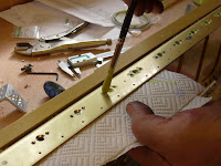
  3. use the drill bit shank to centre the guide piece on the spar flange hole and clamp the guide piece to the flange with the drill bit still in place.
  4. Now I was able to go ahead and countersink to the required depth knowing that my countersink would be centred on the hole, perfectly formed and to the correct depth - result!

Beware that the platenuts for the inspection plates on the bottom flange are smaller than those for the tank skin attach platenuts. The screws along here (4 platenuts at each of 3 locations) are #6, for which #30 is the correct cutter. I don't understand why they call out #40) I still used a guidepiece with a #30 hole as I didn't want to change a winning formula. Having some guide material left with a hole the exact same as the cutter guide pin is essential, otherwise the cutter will wallow around once it breaks out the other side of the flange and starts to enlarge the hole.

I used an artists' brush to spot-prime all the countersinks. I intended to just wipe off the excess but it dried so fast that I couldn't . However, a stanley knife blade worked perfectly with no effect on the anodised flange surface- just like scraping paint off glass after painting a window.


Work was slow today. I expected to get both spars done and the platenuts actually riveted on. The slowness was partly because I had been on a long lay-off from building. I spent longer than I should have foostering around with setting and re-setting the countersink cage. I have two of them, specifically to cut down on re-setting, but three would have been better because I want to keep one permanently set for #40 countersinks at all times and the other was being changed between #30 and #21. If I get another, I can leave it permanently set for #30 and use the third for all other sizes.

Wings unfurled

Monday 14th July (2hr 50min)

Wing kit Inventory

As with the emp, the neatness and inventiveness of the packing is itself a work of art. This evening, I emptied the spar box, broke it up and stowed the contents away before going on to the main parts box. The bag-of-bags containing all the rivets, small hardware and small parts is in the spar box along with the spar centre section and the spars themselves. There is also a bundle of long angle aluminium pieces (longerons for the fuselage and several long parts such as the rear spar, etc.

My main box looked less than full, what with the fuel tank parts having been sent to Evan Johnson for building. The stars here are the composite wing tips and all the various skins. The tips are best stored on a flat surface standing on the inboard edges. The skins obviously need to be stored flat but I have no further 'real estate' in the attic, so the only option is to store them on their edges, tightly sandwiched between the top cover of the packing case and the side wall of the shop. I hinged the crate to the floor at its bottom edge and secured the top edge to the wall with an old leather belt which I cut in two, screwed to the wall and hooked over some screws. This way, I can slip the belts off their hooks and open the thing up like an art portfolio, giving me access to all the skins stored inside.

To protect the skins further, their bottom edges are resting on a piece of cardboard and they also have a sheet of cardboard between them and the wall and another between them and the crate top.

They certainly need protection because, I managed to ding up the corners of two bottom skins next to inspection holes while I was building this storage. It is only a small ding and I should be able to make it dissapear before I hang the affected skins but I have no idea how it happened, except that I am certain they were perfect when I first opened the box. Be careful how you handle your skins. Preferably get someone to help you with them because they are big and floppy and delicate.

Rudder Rolling

Sunday 13th July (3 hr)

Rolled and riveted leading edge of rudder. Put in rivets at narrow end of elevator end ribs. Pop-riveted ribs at narrow end of rudder tip rib.

With a clean shop, I set about finishing off all the left-over jobs from the empennage before settling down to the wing construction phase of the project.

I decided to roll each section of the leading edge separately. These sections are defined by the hinge cut-outs that divide them. Before rolling, I put slight bend in the leading edge of the overlapping skin so that it would lie flat after riveting. Not everybody does this, especially because it is such an inconspicuous spot, but I wanted to get a feel for the process before I get to areas where it may be far more necessary. I used the Isham-supplied tool for the job and I was reasonably happy with the results. There is certainly little or no gap between the skins but the bend that I put in was a little too aggressive and is still visible. It is possible to adjust the gap between the rollers so I may try to have them a little less tight in future. Also, I will probably borrow the Avery's tool from my friend and fellow-builder Bryan Sheane and see how that compares.

For the roll itself, I used a metal tube of just under an inch in diameter. In fact, it is the bottom telecopic section of a lawn umbrella with the plastic fittings removed. This was taped on to the skin using 3M duct tape. I don't think the diameter is critical but a bigger tube will not allow you to over-bend the skin enough so that it springs back to the position you want.

I clamped a vice-grip onto the tube in the hinge openings and rolled the skin making sure that I was also exerting pressure downwards into the bend. This was to prevent any bending of the skin at the point where it crosses the forward edge of the rudder spar. The duct tape adhesive was so strong that removing it threatened to alter the bend just created but, with a little care, it eventually came off. Getting clecos in to the holes was easy at the top but a little harder near the bottom where some hand pressure was needed to get the holes to match up. From there it was a simple matter of drilling out the holes to size and putting in the correct pop-rivets.

Riveting on the skins to the narrow ends of the elevator and rudder ribs was something I had not been looking forward to and had not had any success with until now. My new masonry chisel (with the sharp edge ground off and polished) was a definite improvement. The flats on the handle made it easy to keep everything in position while the rivets were being set. I still had not located rubber grommets of the right size to put over the rivet tail so as to squeeze the skin and rivet flange together but I was able to get the corner of an edge clamp cleco onto the corner of the rib flange close to the rivet without interfering with the job.

Ultimately, however, there just is not enough space in there to set both rivets in the last position, so I had to content myself with pop-rivets on the underside of the elevators and on both sides of the rudder.

First day of 'real' building since the break - and very enjoyable it was too.

How did the shop get this dirty?

Saturday 12th July

Tidied up the Shop

During the nearly 10 week lay-off from the project, I was constantly in and out of the shop to find some tool or other that I needed for the re-modelling job. Apparently, I was not especially tempted to linger, or run a loving finger over the finished emp parts, or even put things back properly.

Consequently, the untidy mess that greeted me when I finally got to begin the wing construction was amazing. It took a solid two hours of sorting out aircraft from non-aircraft bits and tools and putting them away before it looked like a place of work again.

If you think I am going to publish a photo of the state it was in, then think again! I'm not proud of it.

Look at those Tanks!

Tuesday 8th July

Unpacked, examined and stored pre-built tanks

Evan Johnson built my tanks! There, I said it and you know what, I don't care. In fact, EVAN JOHNSON BUILT MY TANKS AND I AM PROUD!

My esteemed Inspector highly recommended this course of action because of the number of cases he has come across of difficult leaks - during construction and also during operation. Having lost more time than I had planned to the recent home remodelling project, I was happy to recover a lot of it in this way. I should now be back on schedule and finish my wings comfortably by the end of the year.

Vans themselves used to offer this option but they now only pre-build tanks as part of a QB wing order. Evan currently charges $975 for the RV-9 tanks. Then there is the shipping cost in both directions to/from Vans and the onward shipping to you will also be a little more as there is now the weight and volume of a third crate, even though the main crate is a little lighter (not smaller).

Vans offered me the facility of taking payment and passing it on to Evan so I did not have to pay him directly.

How it works is that you tell Vans to ship the tank parts to Evan and he ships the finished tanks back to Vans where they join the rest of the wing kit for shipping on to you. He also builds a very nice shipping crate for each tank, lined with polystyrene sheeting so they arrive exactly as they left him. You need to give Evan time to do his thing. I think three months is about right but it has been much longer in the past so check with him in case his lead time has shortened further.

He recommends some extras, such as the delux fuel caps and the fancy screened fuel pick-ups. I agreed to both of these options. Of course you also have to decide on capacitance vs float fuel level senders (I went with floats as I believe the capacitance ones give different readings with different fuel types and I would like to operate on both mogas and avgas). He will also ask you to get Vans to include a quart of tank sealant.

If I was doing it again, I would probably go for the new Andair caps, which are probably better again than the delux models. These fit the original (non-delux) Vans body so it is an upgrade you can make later. However, with the Vans delux model, you get two extra lock bodies for canopy latch and ignition so you only carry one key and you can't refuel with the engine running (as if you would!)

The workmanship is first class. Check these pictures against most other builders' websites and you can see the difference straight away. The most obvious difference is that Evan has obviously sold his soul to somebody he shouldnt, in exchange for the sacred knowledge of how to do tank sealant neatly. Just as importantly, you will never see better riveting. However, just as Persian rug makers deliberately include a mistake in their delicate patterns because only God is capable of perfection, I noticed just one rivet marked "oops".

Evan is also an RV-10 builder and he loves to talk RVs or any other aviation topic. I am very happy that I have chosen this option and I can thoroughly recommend Evan.

Wings arrive!

Monday 7th July

Accepted wings delivery

I had quite a time getting this kit through customs. The European Union has a new 'simplified procedure' for customs clearance which has made things infinitely more complex. To be allowed to import something like this, you need to have 'End-User Authorisation, for which you need a TAN ("Trader Authorisation Number", I believe) for which you need a VAT ("Value Added Tax" - like US sales tax but much higher) number. Of course, being a private individual working on a private strictly non-commercial project, this is not a VATable activity. However, as it happens, I was once registered for VAT a long time ago in relation to a business idea I began to work on but which did not come to pass. In the end, I gave them this number to keep them happy as they were clearly perplexed and going in circles, poor things. The next day, having paid over the VAT and customs clearance fees together with a fairly large sum of money for the additional days storage (11 days in all - you get 5 free) at the docks warehouse, the truck arrived.

Despite requesting one, the truck had no tail lift and I certainly have no cargo handling equipment at home. As it turned out, the driver was more than willing to help. The length of the spar box is an advantage because it is easy to lift just one end down from the 4 ft 6in deck of the truck and then lift the other end. The main box was quite a bit lighter than I had expected (the sizes and weights are all on the Vans website) because of course the parts for the tanks were missing from it.

With the boxes on the street, the truck departed. My advance planning for this situation amounted to buying two 'skates' for moving heavy furniture or appliances. Dorothy and I were about to use these to move the boxes towards the house when a kindly neighbour came along and insisted on lifting them with me. He is retired and a good 10 years older than me and I fully expected him to damage his back but there was no stopping him. I often come across situations like this where I carefully plan how I am going to handle something and someone comes along and takes over, dismissing my plans with "No, no, you don't want that. You want this". It always seems impolite to burst the baloon of their well-intentioned 'expertise'.


Anyway, we got the crates into my front garden (Did I mention that I live in a terraced house where some idiot built an aircraft workshop blocking the entrance to the back garden?) and there I put my foot down and would not allow them to be lifted further. I went back to work and left things until later when I had the field to myself. That evening my daughter's boyfriend was in attendance and he is a much fitter and more amenable young man. Together, Matt and I lifted the long spar box through the hallway and kitchen and out throught the kitchen window - it was too long to make the turn through the doorway.


The spar box was damaged at one end. It may have been the customs people having a little look to ensure I am not building a stealth bomber. Anyway, I opened the top of the spar box to check and everything looked just fine. I also got the top off one of Evan Johnson's tank crates and took a peek. They look terrific. I can't wait to have a proper look.


Light was fading so the crates were just man-handled into the workshop.