Monday 31st December 2007 7 hours 30 min
Re-etched reverse side of HS parts and primed, 2nd coated HS parts. Primed HS skins (2 costs). Cleaned VS parts (except skins) & elevator stiffners. Cleaned rudder skins. 1st coat primed rudder skins.
Alright, it's Christmas not Easter and the proper spelling is "Ecce" but otherwise it seems apt to call attention to a miserable specimen who spends his holidays on such a pursuit as this.
The instructions for the Ekoetch say that you must prime within three hours. However, the primer is taking so long to dry that I could only paint one side of the HS parts yesterday and that means that the Ekoetch was well past that deadline. So I decided to apply further Ekoetch. I was afraid that it would soften the primer on the finished side but it seemed to have no effect so the primer seems to have cured well overnight.
I was trying to get a sequence going and move sets of parts through the cleaning, etching and priming phases in some sort of orderly fashion. However, it is difficult to keep everything in line. Anyway, my spraying technique was a bit better today. I haven't changed the settings on the gun at all, they seem to be okay, though I have nothing to compare them against.
Want to see my Etching?
Sunday 30th December 2007 8 Hours
Etched elevator parts. Cleaned rudder parts except skin. Dimpled R902 spar and R918 attach strips. Drilled deburred and dimpled counterbalance weight and rib. Primed HS parts 1 side.
 Quite a few bits got left behind in the first phase of parts preparation. In some cases, like the R-918 attach strips, it was just that I forgot a step. In others, like the rudder counterbalance weight and ribs, it was because I did not have the #10 drill required. However, I ordered that from Averys along with a few other bits and pieces and they had arrived a few days before the Christmas shut-down.
 I finally got to try some spraying. First I set up the gun using a method I found on the internet. When I had a reasonable flat vertical spray pattern with a rate of flow that was neither too fast or too slow, I began to prepare the primer itself. First I had to dilute it to get the viscosity down to the 20 second mark recommended by Stewarts. Viscosity is measured by timing the stream of paint coming from a hole in the bottom of a special cup that is dipped in the paint and then withdrawn. You start timing when you raise the cup and you stop the clock when the constant stream breaks into drops. The thicker the liquid, the longer this takes. Getting to 20 sec seemed to take an awful lot of water. Incidentally, I could not find distilled water for sale anywhere (chemists [drugstores]paint shops both came up blank) I eventually found de-ionised battery top-up water in a motor accessories store and they assured me it was in fact distilled water. I had to stop at 25 second viscosity because I was approaching the maximum dilution of 33% allowed by the product instructions. Anyway, I thought is was no hard to have the paint a little bit too thick - better than having it too thin.
The spraying went well, I thought, but the paint took a lot longer to dry than I expected. The first lot looked as if it was not going to dry at all. However, after over an hour, it had finally dried. It is supposed to dry within about 20 minutes. I worried that the de-ionised water was chemically active in some way and was preventing the paint from drying.
Washing up
29th December 2hrs 45min
Cleaned HS parts
 This was my first experience of the Stewarts EkoEtch product. It seems very innocuous and I hesitated to dilute it 1:20 in water as instructed. However it is actually very powerful and it takes off Sharpie markings quite effectively. As a result I had to devise a way of identifying the parts so that they will be assembled in the right places for which they were match drilled. However, some parts are duplicated between left and right HS, so I did all the parts for these assemblies in batches and kept them separate.
 I bought a large plastic under-bed storage chest for the cleaning/degreasing operation, on the basis that it would allow me to imerse the maximum size and number of parts in the least amount of fluid. I am not sure if this was really of much benefit. I stored the diluted cleaning fluid in it afterwards as it seemed to have lots of potency left. However, I might have been just as well just making up small amounts in a bowl and dipping my cleaning pad in it as required. I could then have cleaned the parts on my bench, suitably covered with some plastic covering.
 I used the red Scotchbrite pads for this operation and they certainly scuff up the surface nicely. In fact, when the parts were rinsed afterwards, the water sheets off like it is supposed to do after the next etching step. Effectively, the parts have been mechanically etched. This is undoubtedly overkill but I think I will continue with it nonetheless as it is very satisfying to see how well the parts come up once all the tiny scratches dissapear in this scuffing operation.
Spray set up
27th December 5 hr
Setting up for priming
I got a few hours away from the Christmas festivities today to get ready for the priming operation.
 The access to the booth proved a problem because the velcro is so agressive and because,when you pull the sides apart, you are shortening the height of the walls so the floor has to come up. This made getting in and out, particularly in full painting regalia while holding parts, very awkward. Because of this, I taped up the old corner entrance and cut a full-sized roll-up door in one of the side walls. The 'door' was cut from spare Powerclad material as it had to overlap the opening. I re-used the velcor (expensive stuff) tape to fix it to the opening at three points down each side and one across the bottom. This works quite well. When I take the booth down I might consider using a long zip to close the 'door'; just as you would find in a tent. I could then open or close it single handed in one movement.
I found some useful advice on setting up a spray gun in the Stewarts procedures manual and supplemented this with some more information that I found on-line. There was quite a bit of trial and error involved so I taped some newspaper to the inside of the booth and filled the gun with water. Using something with a colour in it would make this trial and error process a lot easier but would create more mess. I didn't want to waste any primer so I just made do. In the end, I got what I thought was a nice narrow vertical oval shaped spray pattern and the liquid seemed to be coming out of the nozzel at a reasonably good rate.
Spray booth
Wed 19th January 2hr 45min and Sat 22nd Hanuary 6hr 30 min


 Finally, I have all the parts ready for priming. In an earlier blog, I have already expressed my views on the priming issue and how I came to decide on using the Stewarts Systems product range to prime the entire interior of the plane. Subsequently, I bought a new HVLP gravity fed spray gun on eBay that I am looking forward to using. Now I need to set up a spray booth that will be easily demountable and will store in a compact format.
 I began by cutting a 24 foot length of powerclad to go around all four sides and form the walls and two six ft. squares for the roof and floor. These were made up into a cube by taping the seams with duct tape. All of this material almost took over the shop! The entrance was originally at the corner where the ends of the 'wall' material came together. I used a length of velcro take to make this join and thought I would easily be able to get in an out through this. It certainly was effective because, with the velcor closed, the thing would stand on its own by virtue of the air trapped inside and would only deflate over a period of 5-10 minutes. However, it was really difficult to open the velcro and climb through. So later, I cut a full sized door attached with tape at the top and fastened with intermittent short lengths of velcro down each side and across the bottom. To make sure it hangs properly, I taped a lenght of timber to the bottom as a weight.
 I put in two lengths of 2X1 timber along opposite sides of the wall-roof join and stappled these to the Powerclad. In use, the booth is suspended from these stiffeners which are hung from the shop ceiling by hooks and ropes fixed into the timber and corresponding hooks in the walls and joists of the shop structure. In order to hold the walls reasonably taut, I covered the floor with some 1/8 in. hardboard that I had in stock.
 Because the thing was so airtight, I decided that I needed to provide for ventilation. A shower fan and cheap plactic ducting leading out through the window provided for the extraction but I also needed a way for the air to get in, otherwise the extractor would to try to deflate
  the booth and suck the walls in. Again, it was important not to have anything still that would create difficulties when rolling up the booth for storage. The answer was a replacement filter for a cooker extraction hood, which comes in a sheet about 30 in. by 24 in. I cut out a corresponding rectangle from the Powerclad and taped this filter material in place with duct tape supplemented by office staples. This should filter out any dust as the air comes in.
Constructed Spraybooth

 Finally, I have all the parts ready for priming. In an earlier blog, I have already expressed my views on the priming issue and how I came to decide on using the Stewarts Systems product range to prime the entire interior of the plane. Subsequently, I bought a new HVLP gravity fed spray gun on eBay that I am looking forward to using. Now I need to set up a spray booth that will be easily demountable and will store in a compact format.
I am trying to use as little stiffening structure as possible as I want to be able to roll this thing up and store it above the rafters of the shop. However, normal polythene sheet ("Visqueen") did not seem to be robust enough. Passing a building site one day, I noticed the material they use for cladding scaffolding. This stuff is a polythene sheet with a 'net' of polythene cord molded into it. It is supplied in horizontal strips 2 meters high and these are joined together top and bottom to form a tarpaulin of the exact height needed for the scaffold. Subsequently, I found that this material is called "Powerclad" and it is available in rolls from scaffolding hire and sales companies. A roll of 60 meters costs €120 plus VAT but luckily, the guys at the place I went to sold me an end of a roll with more than enough left for my needs and charged me very little money.
Some builders have constructed small spray booths with open fronts that just catch overspray. I want something bigger that I can actually get into and paint a reasonable number of parts at a time, including large parts such as empennage skins. I decided on six feet square mainly because that was the length of the pieces of stiffening timber that I bought.
 I began by cutting a 24 foot length of powerclad to go around all four sides and form the walls and two six ft. squares for the roof and floor. These were made up into a cube by taping the seams with duct tape. All of this material almost took over the shop! The entrance was originally at the corner where the ends of the 'wall' material came together. I used a length of velcro take to make this join and thought I would easily be able to get in an out through this. It certainly was effective because, with the velcor closed, the thing would stand on its own by virtue of the air trapped inside and would only deflate over a period of 5-10 minutes. However, it was really difficult to open the velcro and climb through. So later, I cut a full sized door attached with tape at the top and fastened with intermittent short lengths of velcro down each side and across the bottom. To make sure it hangs properly, I taped a lenght of timber to the bottom as a weight.
 I put in two lengths of 2X1 timber along opposite sides of the wall-roof join and stappled these to the Powerclad. In use, the booth is suspended from these stiffeners which are hung from the shop ceiling by hooks and ropes fixed into the timber and corresponding hooks in the walls and joists of the shop structure. In order to hold the walls reasonably taut, I covered the floor with some 1/8 in. hardboard that I had in stock.
 Because the thing was so airtight, I decided that I needed to provide for ventilation. A shower fan and cheap plactic ducting leading out through the window provided for the extraction but I also needed a way for the air to get in, otherwise the extractor would to try to deflate
  the booth and suck the walls in. Again, it was important not to have anything still that would create difficulties when rolling up the booth for storage. The answer was a replacement filter for a cooker extraction hood, which comes in a sheet about 30 in. by 24 in. I cut out a corresponding rectangle from the Powerclad and taped this filter material in place with duct tape supplemented by office staples. This should filter out any dust as the air comes in.
Penance for old sins
Sun 16th Dec 9hrs 30min
Countersunk HS-902-L spar and prepped edges. Cut replacement R-915 A&B stiffeners and match-drilled to rudder skin. Prepped R-915s. Made replacement HS-908 attach angles.
 I did the countersinking of the HS-902 spar flanges to accept the skin dimples. This was the part where I had ruined the original part so I took it easy, making sure that the head of a size 3 countersunk rivet fitted down completely in the countersink so that it does not stop a fingernail drawn across the rivet. On this occassion I was careful to get it just right but I am not entirely certain that the skin dimples are fitting down enough, even if the rivet heads are okay. However, Vans support said clearly that the countersinks need to be set deep enough for the relevant rivets, not the dimple that sits into it.
 The rudder is one of those areas where it is hard to arrange to drill through the parts that have already been match-drilled into the new parts. The skin is very floppy, even with the stiffeners clecoed to it. So, sespit what I said last Thursday, I drilled through the new part into the old. I seem to have got away with it as all the holes seem fine.
I was not happy with the second set of HS-908 attach angles. They were infinitely better than the first set but still a little smaller than the designed dimenions so, as I was having other parts sent, I decided to sport the $5 for the short length of angle required. This time, I marked very carefully and stayed well away from the lines with the bank saw. I then used a hand file and digital calipers to come right down to the exact dimensions required. Finally, I rounded off the corners to match the full-size drawings. They took a surprisingly long time as the 9 HS902/7 attach holes have to be drilled and then the angles have to be match-drilled to the HS-907 doubler and HS-902 spars. In the case of the left attach-angles, I only drilled the location hole and then did the remaining drilling throught the already match-drilled holes in the spar and doubler. Naturally, I clamped a straight edge across the two angles to ensure their bottom webs are in the same plane.
Eventually, I was happy that my HS-908s are spot on and all the other little 'oops' to date had been cleared up. Pity abut that trim tab.
Skinned again
Thurs 14th Dec 2hr 15 min
RE-assembled R-HS skeleton and skin and match-drilled HS902-R
In order to complete the match-drilling of the replacement HS-902, it was necessary to assemble the full skeleton and match drill through each rib into the web of the spar. Then the skeleton had to be assembled in the skin so that the flanges of the spar could be match-drilled to the skin.
This was a simple process and went without significant problems. Of course the skin does not fit as well as on the old spar because it has been dimpled and the spar flanges have not yet been countersunk. Consequently, the skin sits on its dimples and does not yet lie flat against the spar. This knocks out the alignment of the remaining holes in the skin and main ribs so I decided that I would not cleco these for the match-drilling operation.
Finishing the Trim Tab Preparation
Tue 10th Dec 2hr 30 min


 While I am thinking about getting a replacement trim tab skin, I went ahead and prepped this one, in case I decide to use it. This is not the easiest of jobs. It would have been better to prep the edges at the end of the skin before bending the tabs for instance. I tackled the leading edges initially with the spar clecoed in. This was okay for the lower edge but the spar was interfering with getting a good surface on the upper edge so I disassembled it and worked 'free-hand' with the small Scotchbrite wheel in the die grinder.
Prepared the trim tab skin and spar edges. Deburred spar and skin. Countersunk the spar top flange and dimpled the bottom flange holes. Prepared and dimpled the horn pieces. Assembled HS-902 r & L with the HS-907 doubler and match-drilled them.


 While I am thinking about getting a replacement trim tab skin, I went ahead and prepped this one, in case I decide to use it. This is not the easiest of jobs. It would have been better to prep the edges at the end of the skin before bending the tabs for instance. I tackled the leading edges initially with the spar clecoed in. This was okay for the lower edge but the spar was interfering with getting a good surface on the upper edge so I disassembled it and worked 'free-hand' with the small Scotchbrite wheel in the die grinder.
There is no more I can do on the trim tab for the moment so I began work on the recently arrived replacement parts. I started with the HS-902 L and R and the HS-907 front spar doubler. The trick here (and in any situation where you are preparing replacement parts) is to use the holes in the parts that have not been replaced as the 'master' holes for match-drilling the new part. If you drill from the new part into the old, you can get mismatched elongated holes. In this case, there was no problem on the right as both the spar and doubler were new but I was careful to drill from the aft side through the spar into the doubler on the left. This is the opposite direction to the original match-drilling.
Trim tab - Another right mess
Sun 9th Dec 3hrs 10Min
Made bending break. Masked and sanded the site of the trim tab foam ribs. Trimmed the trim tab horns and match-drilled. Completed the Trim Tab trailing edge skin bend. Made blocks and bent end tabs. Match-drilled ends and skin to spar holes.
The replacement HS-902 and HS-907 arrived during the week along with the angle needed to make replacement R-915 A&B stiffeners and the angle to make a third(!) set of HS-908 attach angles. I am looking forward to preparing these pieces and eliminating all my past sins. However, I scarcely have the replacement pieces in my hands when I mess up another piece. This time it is the trim tab skin, but more of that later.
I made the bending break from two of my shelves as they were the only pieces of timber I had of about the right side. They in turn had been made from scraps of half-inch ply that I had left over from building the workshop and I had glued two thicknesses together to get the stiffness I needed for the shelves. The bend was not as smooth as I expected and it seemed to vary depending on where I had leaned on the break. However, I got it straight with a bit of trial and error. When I inserted the spar, I found that it was a little over-bent so I put it over the edge of another piece of half-inch ply and pushed gently down on the trailing edge. This spread the bend out a little until the spar fitted perfectly in position at the 'open' leading edge.


 The manual shows pictures of the set-up for bending the tabs on the skin to form the ends of the trim tab. This is done using interlocking blocks, one of which is cut to go inside the skin and the other goes on top. The whole assembly is positioned on the edge of a bench and clamped tightly. Another picture shows the tab being bent with a mushroom set in a rivet gun. I also watched the Orndorff DVD again but George just refers to having bent the tabs using his flanging tool. I decided to go with the Vans procedure so I made the interlocking blocks from three-quarter inch MDF that I had lying around, clamped it all up and went at it initially with a timber block and a hammer and then finished off with the rivet gun.
 To say the least of it, the results are not good. There were two problems. Firstly, despite heavy clamping, the blocks moved slightly, so the first bend did not end up on the line where it was supposed to be. Secondly, the rivet gun hammered the hell out of the skin leaving it over-bent and all dinged up. Maybe the part is okay from a functional point of view and the problems are only really visible at the edges but I don't think I can live with it.


Afterwards, I searched the forums for other people's ideas. The Orndorff video simply refers to using the flanging tool to make the bends but does not show it. I found that lots of builders have problems with this task, so much so that the replacement skin is with the accessories in the main on-line store rather in "the list" with virtually all of the other kit parts. Those who have done the job successfully are using timber blocks that are much thicker than mine - up to 2 inches. Some have also suggested using double-sided scotch tape between the skin and the blocks to prevent movement. Too bloody late now of course.
Left Elevator completed and on to Trim Tab
Sat 8th Dec 7hr 10min
Dimpled the left elevator skin and stripped vinyl from the inside and from the rivet lines on the outside. Prepped and dimpled the E-902 and E-907. Countersunk the E-907 top flange. Made the E-921 gusset. Made trim tab clamps. Made trim tab ribs and marked their position.
The springiness of the elevator skins makes dimpling awkward. If it was not for the DRDT2, I could not have managed it alone but this dimpler leaves you with one hand for the work and it does the job without too much fuss.
Dimpling the spars was the first outing for my new small diameter dimple dies. Perhaps I could have made do without them but it's great not to have to worry about the die digging into the curve of the metal. I don't have a particular problem with the idea of grinding one side off the full-size dies but as we are only talking about $17 per die, I think it is better to have the correct tool for the job. Postage was effectively free as I had to get a replacement for the #40 countersink cutter anyway.
I have remarked before how tedious it is to set up a countersink cage for a particular rivet size. There is no calibration so it is a trial and error process that takes a lot of time and care to get it right. Even now, having done it three or four times, it still takes 15 minutes or more each time. Some builders recommend getting three countersink cages and leaving one permanently set up for #40, a second for #30. The third is then used for any other sizes that crops up. This would save a lot of time. I think it is worthwhile so I will order two more cages the next time I need something from Avery or Isham.
Making the E-921 gusset was not a problem. I don't have a deadblow hammer so I used a normal hammer with a piece of wood scrap against the metal. I did the bending in my vice, to which I have fitted wooden jaws. While I was fitting out the shop before the kit arrived, I had looked for soft jaws from a number of local tool shops but couldn't find them so eventually I made some from teak scraps and fitted them in place of the metal ones. The teak is hard enough to get a firm grip but I have never noticed any marks on metal pieces that come out of the vice.
I decided to postpone the drilling of the trailing edge for the moment. I may wait until the remainder of the elevator is riveted. If I do that I will have to prime the wedge extrusion on its own as all the other pieces will already have been primed but I feel I will get a better result if the structure is already stiffened up before I set the trailing edge.
 The band saw was very useful for cutting out the V clamps for the trim tab as well as the foam ribs. I don't bother changing back to a timber saw blade for these small jobs. The metal blade does a good job if you give it plenty of time. The belt sander made quick work of tidying up the foam ribs but I had to use sandpaper for the clamps. I finished up the day by marking the location where the ribs will go inside the skin of the trim tab.
Left Elevator Edge Preparation
Tue 4th Dec 1hr 40min
Preped the edges of the Left elevator skin and skeleton parts and trim servo doubler and cover plate
The elevator skins are difficult to handle. My two bench-edge vices with the lengths of timber running between them were a help for the trailing edges. However the elevators are longer than the horizontal stabilisers, vertical stabilisers and rudder and I only had two lengths of timber long enough. Still, I managed by using a shorter piece between the two trailing edges and a clamp in the middle to counteract the bowing of the outer timbers.
The edges around the hinge openings in the leading edge also needed to be prepped. In this case, I held the skin between two lengths of timber lying loosly in my vice. The vices were set to about two thirds of the width of the leading edge so that the skin just rested there in a good position for access. No clamping force was used so it was not held securely and one hand had to be on the work all the time, but it went okay.
When it came to the ends, unlike the VS for example, the elevator was much longer than the height of my table so I had to secure the piece to the table top as best I could and work horizontally over the table's edge. The outboard end was okay as I could get a piece of timber clamped across the section of skin that overlaps the counterbalance assembly and still leave the edge of the skin just overlapping the edge of the table. For the angled outboard end, all I could do was put one clamp on the trailing edge and another on the edge I was working on, moving it as necessary. This provided some support but was not ideal.
I used wet and dry paper on most of these edges (other than the trailing edges) as I felt they were too delicate for the small scotchbrite wheel in the die grinder, especially as the work was not securely held in most cases.
Match-drilling Elevator Stiffeners
Mon 3rd Dec 2hr 30min
Match-drilled stiffeners to left Elevator skin
With the experience of the right elevator, this was no problem. There are two wrinkles: Firstly, all but one of the stiffeners are left-handed (the flange with the holes is to the left of the vertical web when looking forward). This means that when you install them in the top skin, the reverse is true and the flange extends across the skin to the right of the the vertical web. The end effect is that the webs of the top and bottom stiffeners do not interfere with each other because they are separated by the width of the flanges. Secondly, the only exception to this rule is E-908 - R which closes off the edge of the elevator in the recess where it abutts the trim tab. In this case the two webs will lie cheek by cheek with two pop-rivets through the two of them.
The second issue is simpler still. It is that the 5 long E908-L stiffeners go in the full width section of the elevator and the shorter E-909 stiffeners go in the narrower section forward of the trim tab.
The E-616PP trim cover plate is itself a stiffener and is match-drilled in place at this stage also.
On to the Left Elevator
Sunday 2nd Dec 7hrs 40min
Prepared the edges of all remaining right elevator parts. Dimpled the skin. Assembled Left Elevator skeleton and skin and match-drilled all parts. Cut and prepped the edges of skin stiffeners.
 The manual contains plenty of fair warnings about the left elevator. They say that it is responsible for a very large proportion of support calls for the RV-9 kit. Suitably chastened by all this, I got the parts together and began.
I initially cut all the stiffeners to the standard length and did the filing at blunt (forward) end. This was to establish a fixed point from which to measure the length at which the short ones should be cut. Once the first of these short stiffeners was measured off, I decided to cut the whole lot in one go on the band saw (which has been having a quiet time of late). I probably should have taken care to line up the forward holes of all the stiffeners in my stack but I did not think of it and just used the forward end to allign them together. Anyway, the band saw went through them as if through butter and there was none of the 'chatter' and fuss I found when sawing such thin material one piece at a time. Naturally, I stayed well back from the cut line to leave plenty of safety margin and I tidied them up using my belt sander to remove material back to the exact length required. They turned out just fine and not aligning the forward holes does not seem to have caused any problem.
 Match drilling them to the skin was essentially a repeat of the process for the right elevator except that securing the trailing edge of the skin took a little extra ingenuity. The problem is that the 'indent' where the trim tab goes means that most of the trailing edge is not near the edge of the bench where it can be secured (or else the rest of the trailing edge is overhanging the bench and you have nothing to drill into). I came up with the solution pictured here, using scrap timber placed on the bench so that it slightly overlaps the trailing edge and screwing this timber to the bench just beyond this overlap with the edge of the skin.
 The instructions refer to dimpling the E615PP for #6 screws. I don't really understand this as I thought the nut plates would rule that out. I will have to look into this further but for now I just match drilled the holes for riveting the E-615PP to the skin. Incidentally, it is the vinyl that is wrinkled in this photo, not the skin itself.
Right Elevator Skeleton Assembly
Friday 30th Nov 2hrs 40min
Assembled the right Elevator and match-drilled skins, spars and ribs. Disassembled and deburred the skin. Deburred spar and dimpled the top flange. Deburred and dimpled E-906 root rib (except 4 holes at aft end)
 Visually, there was a lot more progress this evening. The work seemed to go much more quickly than yesterday.
You have the choice of using solid rivets to attach the skin to some sections of the bottom of the spar - where you can access them through the hinge openings. I had a look at this and what bothered me was that the pattern would look random. So, I decided I had nothing against pop rivets and chose to use a full line of them across the full width of the spar. This meant driling out to #30 and dimpling accordingly.
 There was the usual problem with dimpling the narrow end of the root rib and I had broken all the nails that came with my pop-rivet dimple dies. I will have to go looking for some tomorrow. I hope I can find them as they look longer and thinner than any I have seen in the stores.
Right Elevator Counterbalance Assembly
Thurs 29th Nov 3hrs 20min
Adjusted counterbalance rib flanges to 90 degrees. Fluted ribs. Assembled counterbalance ribs and skins and matchdrilled ribs to ribs and ribs to skin.
I had a little difficulty 'stretching' the counterbalance skin over the ribs, probably because I left the vinyl on the inside. It is amazing the difference this can make. Perhaps if I took it off, I would be able to fit the skin with less difficulty and wouldn't need the protection against scratches that it provides.
No photos again this evening because of my camera problems. However, while messing with it later, I found that if I turn the flash intensity down the photos are fine so hopefully that will be the end of the problems.
Elevation
Sunday 25th Nov 7 hrs 45 min
 So I rigged the set-up you see pictured here (actually this is the left elevator). I used the wooden cradle from the horizontal stabilisers, clamped one trailing edge to the bench and placed one of my lengths of teak seating rail running between the two cradle blocks. The spring tension in the skin kept the length of teak fairly securely in place. I was working on my sacrificial slab of chipboard again as I needed to drill into the surface. The piece of scrap timber you see under the drill is placed so that the far edge just overlaps the trailing edge where it is 'indented' to allow space for the trim tab. It is screwed down into the chipboard to hold that section of the trailing edge firmly.
Cut and edge-prepped 16 E908 stiffeners for the right Elevator. Match drilled stiffeners to E901-R skin. Dimpled Stiffeners.
Building the elevators, particularly the right elevator, is like a lot like building the rudder. Much of the time today was spent marking out and cutting the stiffeners and then preparing the edges after match-drilling. This time I didn't have to worry about the length of the stiffeners as they are all the same.
The main difference is that the skin is pre-bent so that it wants to stay closed. This makes it quite awkward to gain access to the inside, particularly if you are working alone. I am quite sure that Dorothy (my wife) would be happy to help out if asked but she was away visiting her mother as she does on most Sundays and in any case, I don't want to call on help too often so that I have lots of 'credit' left for the times when I can't do without a second pair of hands.
 So I rigged the set-up you see pictured here (actually this is the left elevator). I used the wooden cradle from the horizontal stabilisers, clamped one trailing edge to the bench and placed one of my lengths of teak seating rail running between the two cradle blocks. The spring tension in the skin kept the length of teak fairly securely in place. I was working on my sacrificial slab of chipboard again as I needed to drill into the surface. The piece of scrap timber you see under the drill is placed so that the far edge just overlaps the trailing edge where it is 'indented' to allow space for the trim tab. It is screwed down into the chipboard to hold that section of the trailing edge firmly.
The tension in the skin is such that it bends up between the clamped trailing edge and the leading edge so it was important to work systematically from the trailing edge forwards and from left to right ensuring that the stiffeners hold the skin perfectly flat.
I kept the blue vinyl in place for this operation as there is a lot of potential for scratches from the stiffners whose edges have still not been polished.
Dimling the stiffeners was done with the pneumatic squeezer.
Rudder Assembly
Monday 19th Nov 2hr 10min
 The manual suggests that you prime and rivet the stiffeners to the skins before assembling the rudder to match-drill the remaining parts. However, I am delaying priming so I clecoed back on the stiffners in order to prevent bowing of the skins. There sure are a lot of holes in this thing.

Assembled rudder and match-drilled skins to ribs, spar and trailing edge. Trimmed rudder brace Fitted and match-drilled rudder brace.
 The manual suggests that you prime and rivet the stiffeners to the skins before assembling the rudder to match-drill the remaining parts. However, I am delaying priming so I clecoed back on the stiffners in order to prevent bowing of the skins. There sure are a lot of holes in this thing.
Trimming the rudder brace was easy and it fitted without any problem. The Orndorff video shows a trim line etched in to the sides of the brace but these have been replaced with twohalf-holes in the edges which you join up with a line, just like on the skin stiffeners. There are also a lot more pre-punched holes in this kit. For instance the R405PD rudder horn to R710 rudder brace holes are now pre-punched in the horn.
Tool Trouble
Thurs 22nd Nov 3hr 50min
 Dimpling the last 3-4 holes at the narrow end of the R-903 and R-904 rudder ribs is very tricky. Even the pop-rivet dimple dies are no use as there is not enough separation between the flanges to get the long nail that pulls the dies together into the holes. I looked on Doug Reeves Vansairforce forums and found various approaches. One is to drill and countersink a piece of mild steel and use it as the female die to make the dimple. Another builder had adapted his DRDT2 dimpler as pictured here.
 I got down to the last two holes on each rib using the pop-rivet dimple dies and I tried using the mild steel die on the final holes with the normal male #40 dimple and a light hammer. However, I am not happy with the results. The test rivet did not sit properly into the hole. This is probably because the countersink cutter did not do its job properly before I thrashed it.

Prepared edges of R-901 skins, R-913 counterbalance skin and rudder ribs. Deburred and dimpled skins and ribs. Set countersink cage for #40 holes on R-916 trailing edge extrusion.
 Dimpling the last 3-4 holes at the narrow end of the R-903 and R-904 rudder ribs is very tricky. Even the pop-rivet dimple dies are no use as there is not enough separation between the flanges to get the long nail that pulls the dies together into the holes. I looked on Doug Reeves Vansairforce forums and found various approaches. One is to drill and countersink a piece of mild steel and use it as the female die to make the dimple. Another builder had adapted his DRDT2 dimpler as pictured here.
 While machine countersinking the hole in the steel with the bench drill and the #40 countersink cutter mounted in the hex adapter (that I usually use for my deburring bit), I managed to break the pilot off the countersink cutter. This was because the steel piece was not held securely and the pilot jammed in the hole when it came up off the table and the hole being countersunk moved out of the vertical plane. That will mean that I can't countersink the R-916 rudder trailing edge until I replace the countersink cutter (or borrow one temporarily from someone else).
 I got down to the last two holes on each rib using the pop-rivet dimple dies and I tried using the mild steel die on the final holes with the normal male #40 dimple and a light hammer. However, I am not happy with the results. The test rivet did not sit properly into the hole. This is probably because the countersink cutter did not do its job properly before I thrashed it.
The final solution I came across was from Dan Checkoway, whose own website is legendary. He says simply bend the flanges out until you can get at them and then bend them back again. However, I wonder if the metal will be work-hardened by this process. In the end, I decided to partly follow Dan's advice. I gently parted the two flanges until I could just get the female pop-rivet die and nail into the last hole. The flange sprang partly back into position once the nail was in, leaving only a small 'permanent' deflection from its normal position. Once the dimple was made, I had to spring the flange slightly further out of position to get the nail head back out. However, after all the dimples were made, I was easily able to get the flanges back to square using the flanging tool. this picture shows a test rivet sitting in the last hole of the R-903.
 simply bend the flanges out until you can get at them and then bend them back again. However, I wonder if the metal will be work-hardened by this process. In the end, I decided to partly follow Dan's advice. I gently parted the two flanges until I could just get the female pop-rivet die and nail into the last hole. The flange sprang partly back into position once the nail was in, leaving only a small 'permanent' deflection from its normal position. Once the dimple was made, I had to spring the flange slightly further out of position to get the nail head back out. However, after all the dimples were made, I was easily able to get the flanges back to square using the flanging tool. this picture shows a test rivet sitting in the last hole of the R-903.
What goes together, must come apart
Wed 21st Nov 2hr 20
Completed R-918 attach strips, fitted and match-drilled them to R-901 skins and R904. Disassembled the rudder and began "DDEP" (Deburr, Dimple, Edge preparation)
Ken Scott replied to an email I had sent Yesterday to Vans support. He says I should replace the HS-902 spar on which some of the countersinks are too deep but the others three spar halves can be used. He also suggested two additional rivets through the skin and stiffeners either side of the double-holes created by mistake when dimpling the stiffeners. I don't like this as I believe the eye will be drawn to the anomaly in the rivet pattern. However the part is very cheap and as I am having a HS-902 shipped across anyway, there will be no additional postage or packing charge. Once they arrive, I can completely eliminate that ding. I also copied my examiner Mick Bevan on this correspondence and he concurs.
Yesterday evening was also the monthly meeting of the SAAC. I always bring a notebook along to record all the useful information and contacts that I get. Yesterday, I got a lead on a torque screwdriver that can handle the very low torque values necessary for the AN3 bolts in the central HS hinge brackets - 20-25 inch pounds. Charles O'Shea also took me through the builders manual that I will be completing with Mick Bevan.
I had already cut the bottom attach strips to length as they come from the same piece as the R-917 shim. As George Orndorff recommends, I cut the two R918 attach strips from the ends of this piece, leaving more than enough for the R917 in the middle. This evening, I cut off the angled ends that butt up to the rudder brace and filed and polished the edges.
They are held in place initially with side-jaw clecos (you need the longer 1" type to reach) and then clecoed as the holes are drilled. The lower holes are not drilled at this stage. The plans simply specify "2" approx spacing" - one of the few places I have seen the abreviation "approx" anywhere on these plans.
Taking the rudder apart took a while as there were so many clecos but that is because I had the stiffners clecoed in as well. I also deburred the skins very lightly.
No photos this evening - The camera is acting up and just could not be persuaded to perform.
Dimple Doh!
Sat 17th Nov 5hr 10min
 The first job is to cut out two stiffners from each length of angle. After trying the band saw, I decided I did not like the way it dealt with the very light material and began to use the snips instead. Initially, I was keeping well away from my lines but I gained in confidence and was soon cutting to the line itself. It was really quite slow and a bit repetitive and tedious to cut them all out and then trim them to length and polish all the edges.
 The Orndorff videos suggest working from one end along each stiffner while match drilling them and cleco every hole as you go. This is to make sure they lie flat inside the skin with no excess skin material between stiffner holes. While I agree with this, I found it necessary to check the correct alignment of all the remaining holes on the stiffner and hold the free end of the stiffner in place while drilling each hole up to the mid point and maybe beyond. Otherwise, I felt that there would be a tendency for a right-left miss-alignment to become established and the holes might not match by the time you reach the far end of the stiffner.
 I had another 'unforced error' when dimpling the stiffners. I don't find the trigger of the pneumatic squeezer easy to use and this caused me to fire the squeezer before I was in position. As a result, I got a brand new dimpled hole adjoining the pre-punched one. A few moments later my wife came into the shop abruptly and gave me a start, causing another missed hole. At least the skins are not affected. I reckon I can make small doublers from the same material and put them behind the affected holes or even spanning three holes. Anyway, I have emailed support at Vans for their opinion.
 Despite careful fluting of the flanges and checking them for 90 degree alignment, I found the rudder counterbalance skin quite difficult to attach. It needs quite a bit of persuasion to match up with the holes in the two ribs. I eventually got it all together. I used a small awl to help align the holes. I put quite an amount of strain on the parts but not to the point of deforming the holes or the skin
Cut stiffners and match drilled to left rudder skin. Prepped stiffner edges and dimpled them. Fluted and prepped tip and counterbalance ribs.
I ordered a spray gun from a British firm on ebay. It looks to be very good value and comes with the correct 1.5mm nozzle to suit the primer I am using. However, it will take a while to arrive and I also need to construct a demountable spraybooth, so I moved on again and made a start on the rudder.
 The first job is to cut out two stiffners from each length of angle. After trying the band saw, I decided I did not like the way it dealt with the very light material and began to use the snips instead. Initially, I was keeping well away from my lines but I gained in confidence and was soon cutting to the line itself. It was really quite slow and a bit repetitive and tedious to cut them all out and then trim them to length and polish all the edges.
 The Orndorff videos suggest working from one end along each stiffner while match drilling them and cleco every hole as you go. This is to make sure they lie flat inside the skin with no excess skin material between stiffner holes. While I agree with this, I found it necessary to check the correct alignment of all the remaining holes on the stiffner and hold the free end of the stiffner in place while drilling each hole up to the mid point and maybe beyond. Otherwise, I felt that there would be a tendency for a right-left miss-alignment to become established and the holes might not match by the time you reach the far end of the stiffner.
  I had another 'unforced error' when dimpling the stiffners. I don't find the trigger of the pneumatic squeezer easy to use and this caused me to fire the squeezer before I was in position. As a result, I got a brand new dimpled hole adjoining the pre-punched one. A few moments later my wife came into the shop abruptly and gave me a start, causing another missed hole. At least the skins are not affected. I reckon I can make small doublers from the same material and put them behind the affected holes or even spanning three holes. Anyway, I have emailed support at Vans for their opinion.
 Despite careful fluting of the flanges and checking them for 90 degree alignment, I found the rudder counterbalance skin quite difficult to attach. It needs quite a bit of persuasion to match up with the holes in the two ribs. I eventually got it all together. I used a small awl to help align the holes. I put quite an amount of strain on the parts but not to the point of deforming the holes or the skin
Edge prep, Countersinking and Dimpling
Wed. 14th Nov 4hr 20min
 I dissassembled the VS and got down to preparing the edges of all the parts. I am particularly pleased with the technique for holding and supporting the edges of the large parts. Even the top and bottom edges of the VS skins proved to be very easy. Those engineering type vices that I got in Lidl and which attach to the edge of my bench were invaluable again. this time, I used some lengths of teak either side of (and between) the two skin edges. Wehn doing the top and bottom, which are a continuous V shape, I just used a shoter piece of timber in the middle..
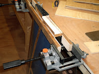
Stripped vinyl from VS 901 skin. Deburred and #40 dimpled skin. Deburred, dimpled and edge preped spars. Prepped edges of skins and VS 808PP doubler. Countersunk fwd side of VS808. Dimpled #30 fwd side of Aft VS803 spar.
I had to go to Roscommon (West of Ireland) for a conference so I rearranged my schedule to work on the project during the afternoon and travel in the evening.
 I dissassembled the VS and got down to preparing the edges of all the parts. I am particularly pleased with the technique for holding and supporting the edges of the large parts. Even the top and bottom edges of the VS skins proved to be very easy. Those engineering type vices that I got in Lidl and which attach to the edge of my bench were invaluable again. this time, I used some lengths of teak either side of (and between) the two skin edges. Wehn doing the top and bottom, which are a continuous V shape, I just used a shoter piece of timber in the middle..
You need to be careful about which holes to countersink on the VS808PP and dimple on the VS803 spar. It helps if you know how the finished unit will be fitted to the fuse. That makes it obvious that the lower end of the forward side of the VS803 needs to be flat so it can can be fitted tight against the bulkhead. That means it has to be dimpled in that area to take countersunk rivets and the doubler plate behind it needs to be countersunk to accept those dimples as it is too thick to be dimpled itself.
Angle of Attachment
Sun. 11th. 8hrs
Measured, cut and finished the HS908 attach angles. Match-drilled them to the forward spar.Started on the HS by assembling the skeleton and match-drilling the skin. Prepared the main nose and cap ribs
Friday was my son’s graduation ceremony (Mechanical Engineering – Trinity College Dublin) so no work on the plane. On Saturday, I just felt like a full day of goofing off and spent some time with my wife for a change. However, today I wanted to tackle this outstanding attach angle project. It went much better this time and I have two perfect attach angles to show for my efforts. I really need to get a finer Sharpie marker however. The so-called ‘fine’ tip is not really fine enough at all and the lines are not precise enough for my liking. It would be good to be able to use a metalwork scribe but that would be to invite stress fractures so its better not to have one in the shop.
 That completed the work in the HS up to primer stage. While I have the primer in stock, I don’t yet have the other elements organised for the priming job.
So, being unable to move on to the assembly of the HS until priming is finished, I moved on to begin the preparation of parts for the next major structure; the Vertical Stabiliser. I believe I may prepare all the emp parts up to primer stage and do all the parts at the same time. This would mean setting up a spray booth just once.
The VS skeleton went together without problems. I thought about using the cradle blocks for the skin and then slipping the skeleton down inside. The manual is silent on how the skeleton should be wrapped. In the end, I just stood the skeleton on the bench and placed the skin over it and then just clecoed the skin on, beginning at the leading edge of the nose spars and working back. This seemed to work really well. It is in huge contrast to the complex assembly method that George Orndorff shows in his video. He was obviously dealing with an earlier kit in which the ribs were formed but not match-drilled. I would safely say that having the skin attachment holes on the rib flanges pre-punched saves at least two hours, if not four.
 I see from his website that Smitty used some 4in foam blocks between the clecos on the underside of his VS to hold it off the table while he match-drilled the top. I decided that the number of clecos involved would distribute the weight well enough. Besides, the clecos are all attached into ribs and/or spars, where there is a lot of structural strength, rather than free-floating skin. Also, the pressure applied to the drill in match-drilling existing pre-punched holes is very small. I was glad that I saved myself the effort of locating suitable foam as the results were perfect.
Countersinking feeling
Thurs 8th Nov. 3hrs 10min
Countersunk forward and aft spar flanges #40. Countersunk spar doublers and aft spar web #30.
Another evening of mistakes. Firstly, I had difficulty working out how to adjust the microstop cage and set it to the correct depth for the intended rivet. There is no measurement gauge (at least on the model I have) so this is a trial and error process and I went through a lot of scrap pieces to get it right (as I thought). Then moving on to the actual work piece, my first countersink was way bigger than the test pieces. Perhaps I did not push the drill fully home on the test pieces. The very first hole is definitely enlarged. I corrected the setting of the cage and went ahead. Looking from the top, it seemed that the countersink was removing material right through to the other side and when I put a #40 drill bit into the hole, it seemed to be very slightly undersized. I rang my inspector about this and he reckoned if that was the case then I should stop. However, when I looked at the holes very carefully with a jeweller’s loupe, I could see that the holes do indeed have a cylindrical section remaining so the countersink did not go all the way through the material. The play that I experienced between the hole and the drill bit was probably because I was using the fluted cutting end . If I had tried with the shank it would probably have been tight. Overall, I have one enlarged hole and I don’t think that will unduly affect the strength of the skin-spar join. After all, it is one of twenty or more along that flange. I will use an oops rivet or make one by slightly compressing an AD3 rivet in the squeezer so that its shank ‘thickens’ while the head remains the same size.
Next mistake was to countersink some of the wrong holes on the forward face of the aft spar doubler. I now have three additional holes that should have stayed flat. There is plenty of warning about this on builder’s sites and I did look carefully at the drawings. I just mis-identified the holes on the actual work piece. I guess I should be more liberal with my markings before I commit to removing material. In sporting parlance, this would be an ‘unforced error’. I think the best thing to do now is to use a countersink rivet in those positions. It’s strength will be similar to a universal head. It is just that the pattern of rivet heads on the finished structure will not be perfect. However this will eventually be hidden under the tailplane fairings.
Left Right, Left Right
Tue. 6th November 2hrs 30min
Stripped plastic from around holes on the outside of the left HS skin. Deburred and dimpled holes. Deburred and dimpled the #40 holes on the main and nose ribs, both sides.
 Yesterday, I emailed Vans support about my problem with the slightly elongated holes in the nose rib. Today, I got an answer from Bruce suggesting that I just go ahead and use the part.
I also posted a question on the RV squadron about polishing the edges in the narrow slot between the tabs and the rest of the flange on the main ribs. I got a variety of suggestions from Scotchbrite pads to 2" Scotchbrite wheels to wet&dry paper. What a great support network!
This evening, I went back to the left HS skin, which was first out of the jig, to bring it to the same stage as the right. So, I stripped off the plastic along the lines of holes, deburred and dimpled. I find the deburring bit mounted in a hex adaptor in my electric screwdriver to be very fast as it is easier to position than the dog-leg manual type. I only need to press the trigger for the briefest moment and then lift off. As the deburring bit has three flutes, one third of a revolution in full contact with the hole is enough to completely remove the burr. It is actually very difficult to restrict the tool to this. I reckon I am getting about one full revolution at a minimum. Still, the holes do not seem to be over-deburred. A deburring bit with only one sharp flute balanced by one or two rounded polished flutes would be a useful tool but I am not about to divert my attention to alter my one and only deburring bit.
This was also the first use of my pneumatic rivet squeezer. I fitted the dimple dies and used it to dimple the rib flanges. It does a superb job very quickly. I need to be careful that the die is properly positioned as it would be so easy to punch trhough beside the hole. I would have preferred to reverse the male and female die but the only way I had space to fit them was with the male die on the plunger. This meant that I was fitting the male die into the hole before pulling the trigger and the work piece would move with the plunger as it travelled up to meet the female die. I would prefer if the work piece was stationery on the male die and the female die did the moving to close the gap (I know you are all thinking up smart double entendre remarks on this theme and all I can say is "Stoppit"!). Anyway, nothing went amiss and I ended up with 16 perfectly dimpled ribs. I even managed to carefully avoid dimpling the tabs on the main ribs as they match up with the inside of the spar flange, which will be countersunk and therefore do not need a dimple in the tab underneath.
Deburred, Dimpled and De-wildered
Tue. 6th November 2hrs 30 min.
Deburred and dimpled the flange holes for skin attachment in the main and nose ribs. Stripped vinyl from left HS. Deburred and dimpled #40 holes
Smitty found that he had to buy dimple dies with a smaller diameter to dimple flanges where the hole is too close to the web. I didn’t have this problem. Perhaps my dimple dies were of a smaller diameter to start with, though they don’t look nearly as small as the ones he eventually bought. I used my pneumatic squeezer for this and it works well. It can feel a little heavy after a few minutes so I found myself sitting down and resting it on my lap as I worked.
 For dimpling skins, the DRDT 2 really is a fine piece of equipment, particularly if you go to the trouble of making up the table according to the drawings they provide. I did have to adjust the height of the table in order to match the height of the lower (usually female dimple dies in their holder so that the skin being dimpled . I did this by attaching ‘skids’ planed to the necessary thickness underneath the feet of the table. I took a measurement after the top surface had been covered with carpet. You do need to be constantly vigilant in positioning the skin so that the male die goes straight through it’s intended hole. It would be so easy to miss the hole and punch straight through the skin.
Dimpled Skin
Mon. 5th November 2007 3hr 55 min
 I ran into another problem this evening with the centre HS 905 nose rib on the right HS. It seems to have moved as I was changing clecoes during the match-drilling operation and I have four elongated holes. Using a digital calipers, I get a measurement of 0.1135 inches by 0.098 (the narrow dimension is correct for a #40). The corresponding holes in the skin are okay. I will have to consult Vans about this.
 The DRDT2 dimpler came into its own for the first time this evening . I clamped the flat metal 'leg' at the rear to the table, which improved stability. The carpeted table also works quite well, sliding in and out nicely and adding support where you need it on larger skins like this. It does tip up when extended all the way forward because I have it on a 2ft deep table, which is not deep enough. I should have moved the other table in front of this one to give me 4ft of depth but I have the two tables set level and I did not want to disturb that. Instead I used a piece of scrap timber between the back of the table surface and the top arm of the dimpling frame, which prevented it from tipping.
 The results are really excellent. It just feels much better to use than whacking your skins with a hammer using the normal C frame dimpler. The motion is like pulling pints of Guiness, which I suppose is genetically implanted in all of us Irish. It is much faster and the quality is consistent. The downside is that it can't be used for riveting, unlike the C frame model. However, I think the speed and repeatable quality is a fair trade for this very rare requirement.
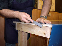
Match-drilled the Right HS. Disassembled. Prepared skin edges. Cut plastic from around holes on the outside of the Right HS skin. Deburred and dimpled the skin.
 I ran into another problem this evening with the centre HS 905 nose rib on the right HS. It seems to have moved as I was changing clecoes during the match-drilling operation and I have four elongated holes. Using a digital calipers, I get a measurement of 0.1135 inches by 0.098 (the narrow dimension is correct for a #40). The corresponding holes in the skin are okay. I will have to consult Vans about this.
 The DRDT2 dimpler came into its own for the first time this evening . I clamped the flat metal 'leg' at the rear to the table, which improved stability. The carpeted table also works quite well, sliding in and out nicely and adding support where you need it on larger skins like this. It does tip up when extended all the way forward because I have it on a 2ft deep table, which is not deep enough. I should have moved the other table in front of this one to give me 4ft of depth but I have the two tables set level and I did not want to disturb that. Instead I used a piece of scrap timber between the back of the table surface and the top arm of the dimpling frame, which prevented it from tipping.
 The results are really excellent. It just feels much better to use than whacking your skins with a hammer using the normal C frame dimpler. The motion is like pulling pints of Guiness, which I suppose is genetically implanted in all of us Irish. It is much faster and the quality is consistent. The downside is that it can't be used for riveting, unlike the C frame model. However, I think the speed and repeatable quality is a fair trade for this very rare requirement.
Subscribe to:
Posts (Atom)

