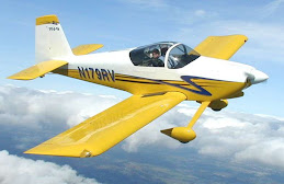
Got it! - proving that I have lost it

Thursday 28th August 2008. 4hr 40min.

Found problem with main rib placement and corrected it. Assembled and riveted main wings to right spar. Riveted right aft spar assembly to main ribs.

With a clear mind, the problem with the main ribs soon became obvious. As I suspected, I had indeed allowed some ribs to be exchanged between the left and right wing sets. However, this had happened at the first assembly stage, so they had been marked as belonging to the wrong set and this was what had confused me yesterday evening. The ribs involved are the three ribs that are tightly spaced under the wing-walk doublers, immediately next to the inboard rib. The inboard rib and the three which follow it should all have their flanges pointing inboard, whereas I had these 3 pointing outboard. A look at the high-res version of the photo of the fully assembled wing skeleton (with bottom skin) that I took a while back confirmed that the orientation was wrong.

So this was easy to fix by swapping the affected ribs between right and left wings. Of course, this means that these ribs have been match-drilled to the wrong spars, skins and stringers. However, I see lots of forum entries on the subject of match-drilling replacement fuselage or wings skins and the conclusion seems to be that holes can be simply drilled out to full size without being assembled to the frames and adjoining skins. The kit seems to be so accurate that match-drilling is somewhat superfluous. Because of this, I fully expect that the ribs will match up with everything else without any problems. We will see, but there was no way I was going to leave them facing the wrong way as it would have made the riveting of the bottom skins very difficult.

So, problem solved (sort of) and on to the riveting. This was easier than I thought it would be. I used Smitty's set up and method, taking out one rib ahead of the one being riveted in order to allow easy access to both sides of the spar at the point being riveted. One thing to watch out for here is that the tip rib is riveted in assembly with the tip rib of the leading edge assembly so it can't be done at this stage - I left it clecoed to the spar. However, I think the aft end of this rib can be riveted to the aft spar and doubler.

The solid reinforcing bars on the forward side of the spar make it a little awkward to set the top and bottom rivet on each rib, particularly at the point where the bar is about the same height as the unset rivet. I switched from my biggest mushroom bucking bar to a rectangular-faced bar for these, so that I was not riveting on the edge of the circular-faced mushroom set. I had also protected the reinforcing bars with medical tape. I used the 1/8 double-offset set in the rivet gun and taped it to the gun with duct tape to keep it from rotating and to keep the gun from scratching the primer on the ribs. With the aft end of each rib still unattached, it was easy to move the rib aside to get a straight shot, so I am not convinced that the double offset rivet set was strictly necessary. I did have to use plenty of clecos, however to ensure that the flange of the rib stayed flush against the spar, while bending the rib out of the way.

Riveting on the aft spar was another job for the air squeezer, this time with the longeron yoke. I had to be careful that the aft flange of each rib was clecoed in its correct place as there are a number of places where it is easy to be confused. Careful attention to rivet sizes and types is also essential here. I decided to go up and down the spar finishing off each size of rivet before going on to the next size because otherwise I would have had to change the gap between sets literally dozens of times during the job.

The end result is very pleasing. Most of the holes in the aft spar are occupied now, the only exceptions being the places where flap and aileron hinges and fairings go.

Going mad!

Wednesday 27th August 2008. 1hr.

Fitted main wing ribs to both spars.

Dorothy is away this week, taking her mother on a short holiday so I am trying to make as much progress as possible. However, things did not go my way this evening.

You would think that it would be simple to put marked parts back in their marked positions but the main ribs would not go onto the spars as per the markings and the plans. Just before starting, I had had a phonecall from my sister, who lives nearby, to say she would like to call by, so I knew I did not have long and this may have contributed to the confusion. To try to sort it out, I fitted the ribs to both spars in case ribs had got mixed between them, even though I thought I had kept the sets apart.

In the end, I just left it there and tried to forget it while I had a great chin-wag with Fanchea (my aforementioned sister). She was suitably impressed with the results of our interior re-modelling project and not at all interested in the plane, which suited the moment perfectly.

Wing structure starts to go together

Tuesday 26th August 2008. 2 hr

Riveted both aft spar assemblies. Riveted #6 inspection platenuts on right wing main spar.

The shop where I bought the compressor (Halfords); a chain of motor parts, accessories and tools suppliers) replaced the regulator for me under guarantee. In fact, after a call through to the manufacturer's help desk, they were willing to swap the entire compressor, but I felt (stupidly, perhaps) that that was too much trouble and it would have involved a trip home to get the current unit. I was just happy to be able to get straight back to work.

With the new regulator installed, I quickly put it to work and began the final assembly of some wing parts for the first time. Platenuts aside, this was the first time I had permanently fixed wing parts to each other and it felt good. It was an easy job for the air squeezer. Having taped up the holes to be left open last night, there was no chance of a boo-boo and that made the work quicker.

I was not happy with the AN470AD4-5 rivets called out for the W907-D and E doublers. They looked too long. I often make my own calculation of the right rivet size rather than take Vans word for it and it is surprising how often they call out really long rivets for the thickness of material involved. I can use my cheap digital calipers to measure the total thickness of the materials but, more often, I look up the thickness of each part in section 4 of the manual and add them up before adding 150% of the rivet shank thickness. Another method is to use the little blue gauge supplied by Isham in their kit. The cut out in the corner for each size of rivet has one side set to 150% of rivet diameter and the other side set to 200%. On this occassion, I decided to use AN470AD4-4s instead and the shop heads still more than filled the shop head gauge.

The missing platenuts from the spars arrived by post today from Vans so I was able to install the final #6 platenuts for the inspection plates on the right wing.

Kaboom!!!

Monday 25th August 2008. 2hr

Tidied up after priming. Assembled both aft spars. Dissassembled left leading edge. Marked leading edge ribs for position. Stripped blue vinyl from rivet lines of left leading edge skin.

It was dark by the time I finished last night, so everything was just thrown back into the shop. This evening had to start with a tidying session to make the shop habitable (and workeable) again.

I had just clecoed the parts of the two aft spars together and set up for the first rivets when I noticed that I had no pressure in the hose, even though the compressor had run normally when I switched it on and had cut out after about the right amount of time. On opening the compressor cabinet, I could see that the regulator knob was missing. I found it on the floor of the cabinet with some other parts. The pressure adjustment knob is plastic and fits to a threaded plastic moulding that screws into the top of the regulator. The knob varies the compression in a spring beneath it, which pushes through a plastic flap sitting on top of a valve between the top outlet chamber and a filter chamber below. Everything above this valve had blown off.

Nothing seemed damaged so I tried just screwing it back. No luck. It just blew again more or less immediately. Fortunately, the compressor was bought new and is just entering the last three weeks of its one year guarantee. I took the complete regulator off to return to the supplier tomorrow.

So I had to find some other jobs to make myself useful for the rest of the evening. Getting the blue vinyl off the rivet lines of the skins is always a good fallback to fill in time. As that involved disassembling the left leading edge, I went on to mark the ribs for position, using the same scheme of punch-marks beside holes that I had used for the main ribs.

Primed and ready

Sunday 24th August 2008. 9hr 15m

Etched main wing ribs and aft spars and doublers and primed them all.

What a long day. Fortunately, it was the first genuine summer's day in Dublin since June. The rest of the summer has been a complete wash-out, for the second year in a row. It makes you wonder whether there will be enough flying weather to justify owning a plane.

I switched back and forwards between the etching parts and priming them. The sunshine was very helpful in drying the parts quickly. On the other hand, when refilling the paint hopper on the gun, the paint was extremely slow to pass through the 125micron strainer I was using. This may be an indication that the paint was too thick but I did not want to over-thin it. On the emp, I felt the paint was too thin by the time it got to the recommended viscosity as measured with a Dupont viscosity cup. this time, I decided to just 'wing' it.
Each of the two coats of primer is itself a two step process, as parts need to be turned to get at the other side. With the spray booth, I can hang quite a lot of parts and avoid having to turn them. Fortunately, the primer dries in about 10-15 minutes (noticeably longer at lower temperatures, as I noticed when evening drew on and the light faded)

As the day wore on, the last parts got etched so I was sitting around waiting for parts to dry so that I could shoot more primer. By that time, I was glad of a chance to just sit in the shop and read ahead through the manual.

Ready to Prime

Saturday 23rd August 2008. 5hr 30min

Completed tank attach platenuts on left spar. Set up for priming. Marked remaining parts "right"/"left". Cleaned ribs for left wing and aft spar parts. Etched and 1st coat primed all aft spar doublers.


My Mum & Dad came for a visit last night so I got a night off. Coming back with a fresh mind to those three platenuts on the aft face of the spar near the root, I eventually got them done without much additional drama. I was probably just tired on Wednesday by the time I got to that job.


So, back to priming. This is not a job I enjoy. I envy builders who just take out a rattle can and shoot, like it was something that barely needed mentioning. This Stewarts primer/sealer system requires two steps (cleaning and etching) before shooting anything. The shooting itself, like all spray painting, involves significant set-up and climbing into a sweaty overall and mask for the job itself. The last time I did it was in winter, so I set up a spray booth, which took up half the workshop and left the remainder very cramped. This time, I am hoping for good weather and I intend to do the spraying outside.

From my experience with the emp, I learned that the cleaner will take off sharpie markings so it is important to mark each part in a way that will still be seen after the primer goes on. As each part on the aft spar is unique, it is only necessary to distinguish between those for the left wing and those for the right. I decided to use a pattern of dots made with the centre punch for this. I chose to use ":.." for left and "..:" for right. This can still be confused depending on which way up you read them so I adopted the convention of always putting them on the aft face of the part , near the bottom.

I had not forgotten how tedious the job of preparing the parts is and it fully lived up to expectations. Cleaning the parts thoroughly with the Stewarts cleaning compound (diluted as per the instructions) and a piece of red Scotchbrite pad is a lot like washing the pots after dinner, which I am also not fond of. Never having been caught short of cash in a restaurant, I have never had to spend most of a day at the sink, but this was a good simulation.


After the scrubbing step, I rinsed off each part and left it to drain (dry if possible). Next it has to be painted with Ekoetch (diluted with an equal volume of water). This has to be left on for about three minutes before thoroughly rinsing the part and letting it dry. At that stage it is finally ready for the primer. Getting a process going to move all the parts through these steps certainly keeps you on your toes.

Dimple Dimple Dimple

Wednesday 20th August 2008 2hrs 50min

Deburred and dimpled remaining left wing main ribs. Dimpled both aft spars. Dimpled J stringers for both wings. Began to install tank attach platenuts on spars.

Still tired (it's the diet and the gym sessions you know), I wanted relatively undemanding work this evening - and there was lots of it. You have to have a certain tolerance for tedium in this game as well as the ability to pace the work over a long project in which the finishing line is so far in the future that it can barely be imagined. This evening was one of those evenings that tested these attributes. I didn't count them but there are a lot of holes in a set of wing main ribs and another bunch of them in the stringers and aft spars. In fact they would be fairly easy to count as there are 15 ribs and the stringers and aft spars involve 6 times the number of rivets across the entire length of the wing. I must do that count in some future idle moment.

The air squeezer is a blessing for this task as it is really fast and provides a consistent pressure on each stroke. You do have to make sure from time to time that the adjustable rivet set (don't even think of getting the non-adjustable kind that relies on shimming out the die with washers) is adjusted to the point where the two dies meet firmly when you close the squeezer with no material between them. I find that this loosens slightly during a long dimpling session and needs fairly constant checking (every 30 strokes or so).

One thing to watch out for is getting so embedded in a rythm that you follow that rythm regardless of whether the work is properly positioned for the stroke or not. This is when you add new holes to your ribs, stiffeners or, worse again, your skins. You need to retain enough concentration to ensure that the guide pin is firmly through the hole EVERY TIME before you pull that trigger.

The Orndorff videos show George using his hand squeezer for this job and it looks as if it would not be much slower than the air squeezer. He holds the saqueezer near vertically with the tip of one handle down on the bench and uses his right hand to move the other handle while his left hand moves the work through the jaws.

I love my DRDT2 dimpler but it is no use on any hole near a flange so it is restricted mainly to sheet material. I am certain that I would hate the usual red hammer-driven C-frame dimpler as much as other builders say they do. Smitty hates it so much that he will use a pop-rivet dimple die to dimple an entire wing skin. As he says, time is what he has most of.

Towards the end of the evening I moved on to one of the last jobs on the spars, which is the riveting of three platenuts near the inboard end that take the tank attachment bolts through the inboard-most attach bracket. These are close to the reinforcement plate and for that reason, the top and bottom one are angled at 45 degrees. However, that does not leave a lot of space to get a bucking bar in between the plate and the barrel of the platenut. The other (forward) side of the spar gets countersunk as the rivets called out here are AD4263-4s and you need a flat surface against which to mount the tank attach brackets. Again the spar structure intereferes here and there is not enough space to get a countersink cage onto the top and bottom-most rivet holes. I used the deburring cutter in my electric screwdriver to countersink these holes, checking regularly with a rivet until I got the right depth.

Whether I am so out of practice in bucking rivets or whether the placing is so awkward, I messed up a few of these rivets and had to drill them out either because they were not properly seated in the countersink on the forward side or because of a faulty shop head. When the same problem started to occur on the second spar I decided to call it a night. It is very important to know when it is better to take a break or persist in the face of a problem.

Weighty issues

Tuesday 19th August 2008. 1hr 30min

Match-drilled bottom left skins. Dissassembled wing. Began deburring and dimpling main ribs.

I was tired this evening but I still wanted to keep progress going so out to the workshop I went to see what I could get done.

Match-drilling the skins is relatively undemanding. I mark the cleco locations on the blue vinyl after the first phase of drilling as it can be confusing to remember in which direction the cleco was moved and which, therefore, is the yet-to-be-drilled hole in the second phase.

I took the wing apart and began the job of deburring and dimpling the main ribs. I only got three done before I just got too tired to continue.

I have a new project by the way. I intend to fit the full Classic Aero Designs interior kit, which of course weighs more than the typical Vans bare-bones interior ( I don't actually know how much because they don't publish that information. I have asked recently but no answer just yet). On the other hand, I intend to fit a very lightweight fully digital panel. However, I already weigh quite a bit myself (like 260lbs!!) and, as I don't want to be limited to flying on my own, I need to loose a lot of that weight. The project is to loose at least as much weight as the total weight of the interior and panel instruments (everything that sticks through the face of the panel) . Any shortfall will have to be met by leaving out bits of the interior kit or panel. That should be plenty of incentive!

I have been at this now for over six weeks and so far I have lost 13lbs, so I was 247 lbs at the last weekly weigh-in. I intend to publish my latest weight in the top line of each blog immediately following the latest weigh-in. Those of you who want to place bets on this should know that the form book records a previous successful attempt which began at an even higher 263 lbs in July'05 and bottomed out 47lbs lower at 216lbs in Feb'06 (shortly before the photo in my profile was taken). Regrettably, I put almost the whole lot back on in the space of only 30 months.

More Stringers

Monday 18th August 2008. 2hr 40min

Match-drilled J stringers to to skins. Removed top skins and fitted bottom skins.

I had the top skins off when I realised that I had forgotten the J stringers, so back on they had to go. I lost about 30 minutes to this mistake.

By the way, I find my (very masculine) workshop apron excellent for this work as it has a large belly pouch. I take a full storage box containing about 150 clecos and just tip them into the pouch before starting to cleco on something big like a wing skin. The pouch also takes the cleco pliers and keeps them to hand. There is another pliers in the toolbox for when I absent-mindedly hide the first one from myself. The pouch also works in reverse to collect clecos when dissassembling.

Match-drilling the J stringers and fitting the bottom skins went exactly like the righthand side but quicker.

Untwisted

Sunday 17th August 2008. 2hr 50min.

Attached platenuts to the left tank. Adjusted wing to eliminate 1/8 inch twist. Match-drilled top skins and leading edge skins to ribs and spars.

Just a short session this morning as, unusually, Dorothy is not travelling to look after her mother, so we decided to go out to visit Russborough house; a beautiful paladian mansion that most recently belonged to the Beit family and has a good art collection. Neither of us have seen it before. We both enjoyed it very much, though we are very spoiled for Georgian splendors in the Dublin area and we have more spectacular treasures at hand.

Installing the platenuts on the tank attach brackets was a simple repeat of the right wing and nothing new emerged.

However, I checked the left wing skeleton for twist using my two plumb-bobs and found that, unlike the 1/32 (negligible) twist on the right wing, I had a 1/8 twist on this one, which is outside the maximum 3/32 allowed. To fix it, I placed a short length of hardwood between the post and the bottom edge of the inboard rib so that it had to be angled slightly to go between them. I then clamped it to the post, which brought it back square and pushed this end of the wing away from the post. As both ends of the spar were clamped to the stand, this twisted the wing back towards square. With a little adjustment, I was able to completely eliminate the twist, with identical measurements from the plumb lines back to the aft spar at both ends.

I checked this set-up a number of times while match-driling as it does not seem as solid as the arrangements that other builders have used (essentially a lower bracket on both posts, made of 3X2) but it did not move.

Back to the Left Wing

Saturday 16th August 2008. 5hr 5min

Dimpled right wing ribs. Assembled left wing skeleton. Fitted leading edge and match-drilled ribs to spar. Fitted splice strip and match drilled to leading edge. Fitted tank and match drilled attach brackets. Match-drilled join strip to tank. Fitted top skins.

All of this was a repeat of the left wing so it happened without drama and much faster. The only difference was that I cut the join strip short to clear the wing flanges and stiffner bars, top and bottom. This still leaves way more edge distance than is needed and does not interfere with the fit of the leading edge or tank skins against the spar flanges. As I see it the join function of the join strip is to join the tank and leading edge smoothly. It has no function in joining both to the spar and it would spoil the fit if the skins if it was left long.

Stringing it together

Friday 15th August 2008. 6hr 35min


Completed match-drilling of top right wing skins. Cut and edge-prepped J channel stringers for both wings. Match-drilled J-channels to right wing skins. Installed bottom skins and match-drilled. Dissassembled right wing. Deburred right wing ribs.


You get 4 lengths of J channel stock in the kit, each long enough to produce the longer outboard stringer. If they made them just a little longer, you could get two of the shorter inboard stingers out of the same length and then they would only have to supply three; unusual for Vans not to have spotted that possible economy.


Fitting is quite simple, though in my small workshop, I had to lift one end of the wing off the stand and move it so that it was pointing towards the open door and then, with the other hand, slide the longer stringer into its place, beginning with one end out through the door. Even with lots of clecos on board, the wing is light enough that this did not count towards my quota of exercise for the day.


The outboard end of the outboard stringer is clamped flush with the edge of the outboard W-903 skin but it is not clear from the instructions wheter the inboard end of the inboard stringer is similarly set flush with the edge of the W-902 inboard skin or with the inboard W-910 rib. The manual says "Clamp the W-926A inboard stringer in place at the W-910 inboard rib, locate it and drill to the skin" which seems ambiguous to me. I went with flush to the edge of the skin on the basis that I can cut it back. However, this leaves me with less overlap. If I am wrong, I could put some extra rivets through both stringers (but not the skin) along the overlap to strengthen the join or I could use some scrap to make a third layer to extend the overlap. Most likely, I will just leave it, even if I have to cut the stringer back to the inboard rib.

I used a small clamp on the stringers at the overlap to make sure they were lying tight together before I began to drill. I pulled out a new drill bit for this operation as I wanted to cut the holes with the minimum of feed pressure on the drill. The line was visible in the centre of all holes as soon as the two end holes were lined up. This required the stringer to be placed tight against the aft edge of the slots in the ribs, but the 'curl' of the J section seems to be perfectly centred in the cut-outs at that position. I would have preferred to work from the centre out but, this being impossible, I worked from both sides inward,, using a line of 6-8 clecos in the holes immediately preceding the one I was drilling and moving them along as I worked. I left a cleco in place at each rib as I passed.

The bottom skins went on without drama. I had to take off the top skins so that I had enough clecos Both leading edges are still clecoed at this point. These two, together with one set of skins, use my full stock of 300 3/32 clecos. In fact, I could do with another dozen so that the bottom skins could be clecoed in every 4th hole all over.

After match-drilling, I took the wing apart and deburred the ribs. If I had followed the Vans sequence, the wing skeleton would be primed and riveted at this point and I would have had to debur and dimple the ribs while assembled. My way is definitely easier and I believe (hope) that the assembly with clecos is firm enough to properly match-drill the skins.


Winging it

Thursday 14th August 2008. 6hr 40min


Marked right wing main ribs for position. Installed W-919 joint strip and W908R leading edge rib, match-drilled to leading edge and removed for deburring and edge preparation. Fitted W-902/903 top skins and match-drilled.


With the tank still off the spar, I began the fitting of the W-908R leading edge rib and the W-919 joint strip that joins the leading edge and tank skins. This strip is sandwiched between the inside of the skin and the W-908 rib underneath. I had been dreading this job, knowing how tight the other ribs had been in the skin. However, it went quite easily. With the rib clecoed to the spar through its aft flange, I pulled the tip end well out of position, leaving about a 2" gap between it and the leading edge. Then I put the join strip in place under the skin. Because the joint strip was still not fixed in position, it was quiet easy to angle it's edge slightly upwards to allow the tip of the rib to pass underneath. As it passed under the edge of the joint strip, I paused to fix the strip in positon on the spar with edge-clamp clecoes over the flanges - the strip had not been trimmed for length and was overhanging.

Thumb pressure was all that was required to move the rib towards its proper position but the join strip wanted to move as well. Initially, I used a pliers to hold on to it while I pushed the rib but this was awkward and the pliers was marking the aluminium. Instead, I drilled through one of the forward-most pre-punched holes and the join strip. This held the strip in positon until close to the end. Eventually the rib flange hit that cleco and it had to come out to allow the rib to be moved into its final position. By this stage the surfaces are all more or less parallel so the forces involved were smaller and the strip did not move out of position.

After a bit more pushing and pulling to get everyting exactly right, I was satisfied enough to put the tank back in place and then match drill the join strip to the leading edge skin and end rib, clecoing every hole as I went. I didn't match-drill the holes for the tank attach screws just yet as I would prefer to see a perfect join with the top skins fitted before I do that.

I marked the ends of the join strip to be cut off flush with the aft edge of the tank and leading edge skins but I am not sure about this. I can't make out from the plans or the manual where the strip should be cut off. It seems to me that they should not be allowed to run aft between the tank and leading edge skins and the spar flange as that would raise these skins above the top of the upper wing skins immediately behind. However on the basis that you can always cut more but you can never put material back, I decided to cut them off flush with the aft ends of the skin for now. The strip and end rib had to come out to allow this to happen but putting them back after the cuts was easy once I knew how.


I got both sets of W-902 inboard top skins out and prepared both wing-walk doublers while I was at it. To save the worktable surface, I did this on my sacrificial sheet of chipboard, setting the forward edge of the wing-walk doublers back by the required amount from the forward edge of the W-902. Fitting the skins was a non-event as they overlap each other and simply but up against the tank and leading edge skins. Again, the join was spot on.


Though I started the match-drilling, I didn't finish out. That's a whole lot of holes! I better get Dorothy mentally prepared before we start to rivet them

It looks like a wing!

Wednesday 13th August 2008. 4hr 15min

Mounted leading edge assembly on right spar and clecoed in position. Mounted tank on right spar and clecoed in position. Match-drilled leading edge skins to ribs and spar and rib aft flanges to spar. Match drilled tank attach brackets to spar. Removed tank and fitted platenuts to tank attach ("Z") brackets

I decided not to disassemble the right skeleton, as I had done with the left, and instead I carried on to fit and match-drill all the wing skins to the skeleton. In that way, the ribs will be fully prepared before I go on to prime and assemble them. If I followed the Vans instructions exactly, I would be match-drilling, deburring and dimpling the top and bottom flanges of the ribs after final assembly of the skeleton and (presumably) after they were primed. I don't think that is a great idea. Probably, the priming would survive the deburring and dimpling but my way seems better. I am only sorry that I did not think of this before disassembling the left wing skeleton as that was a waste of time -


I needed to take the sag, which was considerable, out of the wings by stretching a fishing line between clecos inserted in the two end-most skin attach holes on the top flange of the spar. Once that was done, the join between tank and leading edge was perfect. With such a good fit, I was confident enough to go ahead and match-drill the leading edge skins to the spar and match drill up through the spar into the aft flanges of the leading edge ribs. Changing to a #12 bit for the AN3 bolts, I also match-drilled through the spar into the tank attach brackets. I didn't have a drill stop big enough for the #12 bit so I took it extra-easy to avoid punching through the back of the tank just over an inch behind.

Next step was to fit the tank attach platenuts to the tank attach brackets (three on each except the inboard one, where the platenuts go on the aft side of the spar). The manual advises that these platenuts should be fitted before the brackets are riveted to the back of the tanks as it is difficult to do afterwards. The manual is right on this point; it is difficult. However my pre-built tanks did not allow me this luxury as the brackets are already attached. The problem is that there is not enough room behind the bracket to allow the squeezer yoke to be positioned straight on to the rivet and there is certainly not enough room to hold the moving set against the outer machine head of the rivet to hold it in place before the squeeze begins. A hand squeezer would be better here, but with an air squeezer you have to start with the squeezer at a slight angle and neither set actually touching the rivet. Then, once the squeeze is completed and the yoke is firmly clamped on the bracket and squeezed rivet, everything wants to become square and parallel and in that position, the thicker end of the yoke near the U bend doesn't have enough space any more and pushes against the back of the tank, putting leverage on the bracket and twisting it out of position. Fortunately the extent of this twist is not enough to permanently move the bracket and it springs back into position (I hope).


With care and good trigger control (on the air squeezer) it is possible to get the rivets properly set. However, I was not able to get the factory head as fully flush with the surface of the bracket as I would like (nowhere near bad enough to get a finger nail under them, so not in the 'reject' class, but just not good enough). Not wanting any disturbance to the fit of the tank brackets against the spar (which would have thrown the screw - platenut alignment out and messed up the seam with the adjoining skins), I decided to shave off the tops of these rivets with a file and polish them afterwards with a small scotchbrite wheel on a die-grinder. In any case, rivets in a platenut are not actually structural. Their purpose is only to hold the platenut in position and withstand the torsional forces while the screw is being inserted. It is the screw itself that carries the structural load.

Wing skeleton

Tuesday 12th August 2008. 7hr 15 min

Dimpled access plates. Removed 5th rib from leading edge and drilled out aft flange to clear main spar rivet heads befor replacing ribs in their respective leading edge assemblies. Assembled the left wing skeleton. Match-drilled ribs to spars. Marked ribs for position. Dissasembled and deburred. Assembled right wing skeleton and match drilled.

Even though it could be done much later, the instructions mention dimpling the inspection plates, so I decided to oblige. I am colouring each instruction with day-glow highlight marker when it is done and it has become something of an obsession to get as much as possible high-lighted - especially if it means covering the last patches of un-highlighted text on any particular page.

I assembled the left wing skeleton with clecos and match drilled it before taking it apart again and deburring all holes. I then went on to assemble the right wing.

While building the emp, I had difficulty getting ribs and stiffners back to their match-drilled positions because the sharpie markings came off at the etching (or even cleaning) stage. So, I came up with a system that uses a punch mark in conjunction with the pre-punched rivet holes in the flanges of each rib as a code to indicate position. To designate the outboard right wing rib as No.1, I put a punch mark to the right of the first hole on the bottom flange next to the aft spar. The next inboard rib is No.2 so it gets a punch mark to the right of the second hole from the aft spar, and so on for the remaining 13. On the left wing, the same will apply except that the punch marks will be to the left of the rivet hole. Leading edge ribs will be identified in the same way in a separate numbering sequence of their own - foolproof!

Plate nuts and Brackets

Monday 11th August 2008, 6hr 55min

Installed platenuts on right spar. Installed mid-section attach nutplates on both spars. Installed tie-down brackets and bell-crank brackets on both spars. Added hardwood bearing plates to wing stand brackets.

Great wedding -over 200 present! Always nice to meet Dorothy's extended family again. Since this project began, I am not visiting Athlone (or Kilkenny, where my own family are based) as often as I would like.

Having installed the tie-down brackets, I found that I had drilled and installed the W-933R tie-down bracket upside down (with the tapped end facing upwards). As the nutplates for the bell-crank brackets are not symetrically placed on the tie-down bracket, it was not possible to just reverse it. Solution? - Just tap the other end of the bracket of course.

It turned out that Vans have sent the wrong platenuts with the new spars. The ones marked K1000-06 (for the inspection plates) were huge and definitely not 'as advertised'. The others were marked K1100-06 but it was -08 I needed to attach the tanks. There were plenty more K1100-08s elsewhere in the kit so I was not stuck for those - just for the moment, but there are no other K1000-06s so I will have to wait for Vans to send the right ones. Fortunately, these are to join the inspection hatches to the bottom spar flange so they can be installed at any time up to first flight. I installed the 62 K1100-08s and finished up.


Catching up

Friday 8th August 2008. 4hr, 45min


Drilled and countersunk right spar. Primed all countersinks. Installed platenuts on left spar.


I finished the countersinking, using the same method as before (clamping a piece of waste with the right size hole for the countersink cutter underneath the pre-punched and reamed-out hole). This is slow but gives very nice results.


I really wish I had a third countersink cage. Without it, I had to swap between the #30 and #21 cutters a few times but at least I was able to leave the #40 cutter properly set in its cage. That cage will not be re-set for the rest of the project. Whatever tools I have to order next (and it is certain that there will be another order at some stage - probably soon) I will certainly get another cage for permanent use with the #30 cutter.

I primed all the countersinks at the same time, using an artists brush and a stanley blade to scrape off the set-but-not-cured primer off the top surfaces of the flanges afterwards.


I have now reached the point where I was when I discovered the spar under-bend problem. That was on the 21st July. Not bad to have the problem fully worked out (almost) within less than three weeks. I put the original spars back in the new Vans crate today before I began work and I am now waiting on the shippers to pick them up.

Dorothy and I are off to a family wedding (her 1st cousin) in Athlone for the weekend. Just as well:-5 full days on the trot is plenty and I need a break.

Leading with the Left

Thursday 7th August 2008. 6hr, 20min

Built wing stand. Assembled left leading edge. Received new spars. Drilled out and countersunk platenut holes on left spar.

The posts for the wing stand went up today. I left a 133" gap between them as recommended by Smitty. The advice he got was to put the brackets at 'chest height'. I interpreted this as being about arm-pit height which, for me, is 50". I am pretty certain now that this is too high for comfort by about 5"-6".


The replacement spars arrived. There had been some confusion caused by the shippers about who was paying for freight so I had to shell out €285 to take delivery, which I will get back. There is not much else for me to do at this stage so I need the spars in order to maintain progress, otherwise, I would have delayed and let them sort themselves out.

I went straight to work on them and had finished countersinking the 74 holes on the left spar by the time I finished this evening.

Sorry, no photos tonight. In fact, I don't know where I have put my camera. I suppose it will turn up.

Course Correction

Wednesday 6th August 2008, 1hr 40min

Completed reversal of leading edge ribs. Rearranged the workshop for wing construction. Glued posts for wing stand.

I wrestled the remaining ribs out of the leading edge and wrestled the correct ones in. None of them were easy - I definitely should have just disassembled the whole thing and started again. I bought more duct tape this morning so I was able to pad the saddles for the leading edge, which are now a perfect fit.

I had decided to erect the wing stand over to one side of the shop, leaving enough room to move around the back. This required me to move all three worktables across the shop to line up under the windows. With the castor arrangement, this was not a problem.

I could not find 4X4 lumber for the posts of the wing stand so I had bought 2X4s planed. This stuff was refered to in the store as "CLS". I don't know what that means but it was beautifully straight, nicely planed with radiused corners and had tight core-wood rings, indicating that it was likely to stay straight. I can't understand why it was so cheap ((€4.40 for an 8' length). Construction timber grows very fast in Ireland but it is not of a high quality like this stuff.
Anyway, I glued four lengths together in pairs back to back, with the rings on the end of the posts looking like this: [))][((]. I glued and clamped them overnight.

Wrestling with the leading edge skin

Tuesday 5th August 2008 5hrs 20 min

Drilled conduit holes in main ribs and deburred. Countersunk outboard holes in W-907A aft spars. Made Leading edge cradles. Assembled right leading edge.

I am going with the conduit option, though I have not decided what lighting set-up to go with. Not to put it in would seem to limit my options. There is no guidance as to the optimum placing of the 3/4in hole for the conduit so I placed it by eye in the centre of the area suggested by the instructions downloadable from the Vans site. I initially drilled a #40 hole and then used that to back-drill a scrap of aluminium jammed up against the lower flange and placed with its edge against the the edge of the vertical stiffening indentation - basically any landmarks that were convenient and would be the same on every rib. Using this template, I put the same #40 hole in every rib and then opened them out to 1/4in - the minimum dimension on my unibit. Then, I opened the hole out to 3/4in with the unibit before finally deburring the edges of the hole on both sides - not that they needed it much as the unibit gives a very clean hole.

Countersinking the spars was a step I had left out so I decided to catch up on it now. I had to research how to approach the need for flush rivet heads on the outboard doubler holes that go under the outboard aileron attach brackets. The .040 material of both the doubler and spar are too thin to countersink for a #30 hole though that material can be successfully dimpled. I did not want to also dimple the aft flange of the nose rib that gets riveted with these two so I decided to countersink the spar which is the 'meat' in the sandwich comprised of the doubler and the rib. This will leave a flat surface on the forward face of the spar under the rib.

The countersinking operation is standard except that the top hole is too close to the flange of the spar for the countersink cage. It is possible to cut away the flange of the cage to get closer but I did not feel like doing that so I removed the cutter and used it in the hex adapter that is normally used for the hole deburring cutter. The slow electric screwdriver was not giving good results so I switched to the the high-speed air drill. This was still not nearly as good as the countersink cage but I think it is easily good enough for this situation.
I made the cradles from the HS cradles. There is plenty of timber in them for the size of the leading edge. I used a rib to mark out the shape and then cut outside this line with a jigsaw to allow clearance for some padding. As it happened, I was out of duct tape and decided to go ahead without the padding anyway. This didn't work out so well as the cradles were loose around the leading edge. However, the blue vinyl was (just about) enough protection for the time being.

I began by attaching each rib in position on the skin with the two forward-most holes on the bottom. This was done with the skin out of the cradle and was just to fix the ribs reasonably firmly in the right positon. Next I put the assembly into the cradle, which forced the skin to wrap around the top of the ribs. Getting the rest of the holes to match up was a real pain. The temptation to use the awl was huge and I did, in fact, use it to help line things up. However, I did not exert any leverage on the holes that would have come close to damaging their edges. In any case, the match-drilling stage should sort out any minor imperfections caused by the awl.

Having done the whole leading edge, I became suspicious and found that I had the right hand leading edge skin but the ribs were for the left leading edge. They were all facing the wrong way! Swapping them around one-by one turned out to be slow. I probably should have just started again with the left skin. It took the best part of an hour to do three of the six and at that stage it was long past time to quit.

Edgy

30th, 31st July, 1st, 2nd and 3rd August 2008 20hrs 45min

Prepared edges of main and leading edge nose ribs for both wings.

This was a complete head-wrecker! Pure monotony! The only way to get through it was to put the shop radio on and do it methodically. Normally, I find that talk radio or music lessens your concentration and can lead to mistakes. However, for this job, it was exactly what was required because brain-power is a distinct disadvantage for such a repetitive task.

There are 30 main wing ribs (in six different flavours) and 16 leading edge nose ribs (4 flavours) to be done. I am lucky, I didn't have to do the tank ribs as Evan Johnson has done them for me. That would have been another 12 or so.

The routine was to:

  • Set the flanges to 90 degrees with the flanging tool.
  • Straighten the rib using the fluting tool
  • File the long edges of all flanges with my big file
  • Use small half-round and 'rat's tail' files for the edges of all the notches and corner cut-outs.
  • Deburr all long edges using a combination of my two deburring tools.
  • Deburr the inside edges of the lightening holes
  • Sand the edges in all notches with very fine wet&dry paper
  • Polish the long edges (and some corner notches wherever possible) on the Scotchbrite wheel.
  • Polish the lightening hole edges with a small Scotchbrite wheel on a die grinder.
  • Repeat 46 times
There is no way either deburring tool was going into the small notches without making things much worse. I just had to rely on moving the sandpaper around to knock off any burrs in these areas.

On average, it was taking nearly half an hour for each rib, though I broke it down into a series of sub-operations and ran through the set several times. This was to get a rythm going by having a shorter cycle to repeat.

Luckily, there are not many half-hour operations in the project that you have to repeat 46 times. Anyway, it's done now and won't need to be repeated as all the ribs for both wings have been completed.