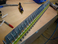
Thin-end rivets
Set last rivets at narrow end of elevator root and tip ribs except for the very last ones. Experimented with techniques for these last rivets.
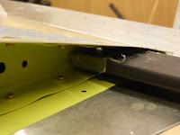
The long-nose no-hole yoke is the obvious tool for this job and does well up to a point (yes that was a pun) where there is just not enough room for the unsqueezed shop end of the rivet as well as the pointy end of the yoke within the flanges of the rib down near the trailing edge.
On most of them, I was able to get the yoke nose in as long as the rivet was not fully inserted. You are then depending on getting the moving rivet set to push the rivet home as it closes before finally setting the rivet at the end of its travel. To do this, you have to have pretty good trigger control skills to get the squeezer to close slowly. Even then, I found that the skin and rib were not tight to each other at the point where the rivet set enough to grab the inside of the holes. These all had to be drilled out, leaving me with only one of the eight where the results were okay. To make matters worse, if you do happen to get one of these set, the rivet head now restricts the space further for setting the rivet on the surface opposite.
I decided to try the 'lever' method so I put some tape around the end of a piece of flat steel bar that I had. However, this wasn't really stiff enough to set the rivet properly, leading to some more drilled out rivets. I will have to look at using a wide 'bolster' masonry chisel, which should be really hard while still being thin enough to get into the space available. Also, I need a rubber grommet with a thickness closely matching the projecting shop tail of the rivet. Placed over the rivet tail, this will push down on the rib flange making sure that the two materials are in close contact as the rivet 'bites'.
That's it with the project for the moment. I really need to help Dorothy out with the remodelling job so I will have to stop work until that is done and the wings arrive. I still have these rivets to finish plus I haven't rolled the forward edge of the rudder skins. Still, building a plane doesn't mean you are no longer a member of the family and duty calls.
Trim tab hinged.
Bent and cut trim tab hinge pin. Trimmed and fitted elevator counterbalance weights.
Bending the hinge pin is not as easy as you would imagine. I marked where I wanted the centre of the first bend to be and heated the spot with a plumbers buthane blow torch until it was bright orange. By now the mark had dissapeared of course but I guessed that the centre of the heated area was the intended centre of the bend. Using my long -nose pliers, I grabbed the pin to the outside of what I thought was the centre point and twisted it over to create the tightest right-angle bend I could manage. it was surprising how much force it still needed and how quickly it regained its strength as it cooled.
Now, with the pin back in the hinge and the right-angled part hanging down ofer the inboard edge of the elevator, I marked where I wanted the centre of the next bend - about an 1/8th from the trim tab spar. Once again, the mark served only as an aiming point for the blow torch but the bend worked out just fine. It only remained to mark and cut off the unwanted tail and clean up the end on the Scotchbrite wheel. The finished item sits beautifully against the elevator trim spar.
I would like to have done as builders of other models have done and use one 'ear' from the hinge scrap screwed into a nutplate to hold the hinge wire in place. However, there does not seem to be enough space for the nutplate at the end of the trim spar on the forward side so I will probably have to just safety wire it as per the plans. I will leave this until later in case I think of some way around the problem.
The trim tab bottom skin's forward edge was interfering with the aft edge of the bottom skin and spar of the elevator, so I needed to bend this upward so that it just cleared this obstruction when the trim tab is deflected downward. I found the best way of doing this was to take the trim tab off and bend the entire length of the skin edge at the same time by pressing it against my bench.
I have heard of builders having problems in sawing the counterbalance weights because the band saw blade starts melting the lead. I saw no sign of this problem, maybe because my blade travels slower or because of the 16 tpi pitch. I did need to file some material from the top and bottom edges of the weights to get them to fit inside the flanges and rivets of the counterbalance arm webs. I hope this will not be a problem when it comes to balancing the elevators at final assembly. The weights are supposed to be too heavy so that material is removed rather than added in order to achieve balance.
I torqued up the nuts to 25 in-lbs and used Loctite to secure them.
Trim tab hinge
Riveted hinge to trim tab skin and top spar flange. Match-drilled hinge to left elevator trim spar.
I used my air squeezer for the easy job of putting in the solid rivets to join the hinge, spar and top skin. The other part of the hinge had not yet been trimmed to length at this stage.
You can see from the paint on my overalls that I have already begun to get involved in the remodelling job in our reception rooms. Dorothy started on this a few weeks ago and it has long been planned that I would join in for the six to eight weeks that the wing kit will be en route to get here. In fact, the kit is already shipped so I am racing to get the emp finished quickly before Dorothy gets to the bits that she can't do on her own.
Next, I joined the two halves of the hinge and positioned the trim tab and hinge on the elevator, using a level as a straight edge to align the trailing edges. It's nice to have the inboard edges match up but it is more important to get the minimum 3/32 inch clearance in the gap between the outboard edge of the trim tab and the adjoining edge of the elevator trailing edge. I just about got away with it as the bend of the end tabs of the trim tab are not razor sharp so the ends bulge out a tiny bit further than they should, adding slightly to the overall length.
I clamped the hinge to the underside of the elevator trim spar at the inboard end only, using an edge-clamp cleco. This held things well enough to match-drill the first hole. From there, I just put clecos in every hole as it was drilled. I felt no need to support the hinge up under the trim spar along its full length for this operation.
Once finished, I drew out the pin and cut off the extra length of the hinge, leving a margin which I filed back flush with the inboard edge of the elevator and then polished up with the scotchbrite 1" wheel in the die grinder.
Rudder Trailing Edge Riveting
Riveted rudder and left & right elevator trailing edges. Pop-riveted trim tab end tabs and trim tab horn. Match-drilled hinge to trim tab upper skin & spar and cut to length.
It is a week now since 'tank sealant day' so I went back to work and began by removing the clecos and cleaning the little stray bits of solidified tank sealant out of the dimples and holes. The edges are still laser-straight at this stage but it is the riveted end-product that counts. I did notice one place where the tank sealant was lifting the skin off the trailing edge wedge very slightly. Obviously, this was close to the end of the sealing job when the sealant was getting very stiff and lumpy and difficult to spread.
The idea here is to half set each rivet with a back-riveting set, flip it over and then finish by riveting on the manufactured head with a mushroom set. In the event, I was not very comfortable with the back-rivet set and decided to try the air squeezer with the gap set to squeeze each rivet just enough to fix it in place. I found this easier although I had to be careful to exert enough pressure on the manufactured head with the non-moving side of the squeezer to ensure it was fully seated in its dimple before it was fixed in place. I worked on every fifth rivet from the centre out and then went back to do the rest randomly.
I was very pleased with the results. I would call it perfect if it were not for that little bump caused by tank sealant and I think the edge material is microscopically dented by the action of the rivet set at each rivet site. It certainly no longer looks like pristine new aluminium sheet but I think paint will hide that completely.
Another anxiety-causing job off the list!
With time on my hands, I went on to pop rivet the control horn to the trim tab. If I had not forgotten this step before 'tank sealant day', I could have easily done these with solid rivets using the longeron yoke. In fact, I should also have solid riveted the bottom skin-spar join at that stage so that will also have to be pop-riveted. The manual quotes MK-319-BS pop rivets as an alternative here. However, I don't have enough of these rivets to cover all locations where they are called out or are an option. I will have to get 30 more from Vans.
I also put pop rivets into the ends of the trim tabs and match-drilled the hinge to the underside of the top flange of the spar. I got this dead wrong first time but fortunately caught my mistake before I had cut the hinge so I was able to re-position the hinge and match-drill again. The first set of holes won't do any harm and can be regarded as 'lightening' holes - if they are ever noticed in such a well-hidden location.
Trailing edges sealed
Attached 2nd aluminium angle to edge of bench. Positioned HS and elevator assembly with counterbalance arms in line. drilled trailing edges to angle and clecoed. Cleared bench for rudder and rearranged shop. Cleaned AEX wedge of elevators. Cleaned skins inside trailing edge. Mixed tank sealant. Sealed in trailing edge in left and right elevators, sealed foam ribs into trim tab.
With the entire HS/elevator assembly in place on the worktables, I attached the remaining part of the aluminum angle I had bought (the first part was used on the rudder) under the trailing edge of the left elevator (now located on the right, as the assembly is upside down to allow the elevator control horns to stick up rather than down) One of the counterbalance arms had initially been about 1cm out of alignment but by the time everything was weighed down and the trailing edge clamped to the angles, it was all perfectly aligned again. I match-drilled through the trailing edge into the aluminium angle, putting a cleco in every hole. I worked from the centre outwards as I feel this is more likely to avoid any waves or curves in the trailing edges.
Elevators attached
There seem to be two risks in finishing the elevator trailing edges. the first is that you produce a hooked or wavy edge and the second is that you build in a twist so that one elevator counterbalance horn is out of trail with the HS (either high or low) when the other horn is perfectly aligned with its HS and the trailing edges are also perfectly aligned. This twist is locked in by riveting the tip ribs and trailing edges and the solution seems to be to drill out these rivets and allow the elevators to 'relax' into alignment. I planned to avoid this by having the HS and both elevators assembled and aligned while I riveted the trailing edge.
Today, I began to implement this plan. I reversed the heavy aluminium angle that I have set into the top and edge of one worktable so that the vertical flange was screwed to the side of the table and the horizontal flange was flush with the top and extending out from it. Then I attached both elevators to the HS (BTW, there seems to be plenty of space to get the bolts in if your fingers are in any way nimble). I propped up the front of the HS with some timber under its forward spar until everything was 'in trail'. With one counterbalance clamped to the HS, the other was initially just 1cm or so out of true
This was the first time I had seen these three parts assembled- the horizontal surface area of the thing is vast!
Movng towards the (trailing) edge
I spent the day finishing all the remaining jobs on the rudder and both elevators to get them ready for prosealing the trailing edge. ,
Earlier, Vans had sent me the 3.5oz size in the cartridge instead of the 1 oz size that I had ordered. From all I had heard, this job is very messy so the cartridge format of the 3.5 oz seemed like a good idea and I decided to order the dispenser gun that goes with it. By the way, the only difference between the gun that Vans sells and the cheapest gun you can get at your local hardware store is in the diameter of the disk at the head of the plunger. If I had it to do again, I would find a way of reducing the diamater of this disk on a cheap gun until it fitted into the end of the proseal cartridge.
The downside of the cartridge is that it is all mixed at the same time and goes off at the same time so you have to have everything that you want to use it for set up and ready at the same time. I have a heavy aluminium angle set into the edge of one of my worktables but this was not going to be enough to do both elevator trailing edges and the rudder trailing at the same time so I had bought an extra 8' length of 35mm x 35mm x4mm aluminium angle. I cut a piece off this to suit the length of the trailing edge of the rudder and match-drilled it to the existing holes in the skins and trailing edge web.